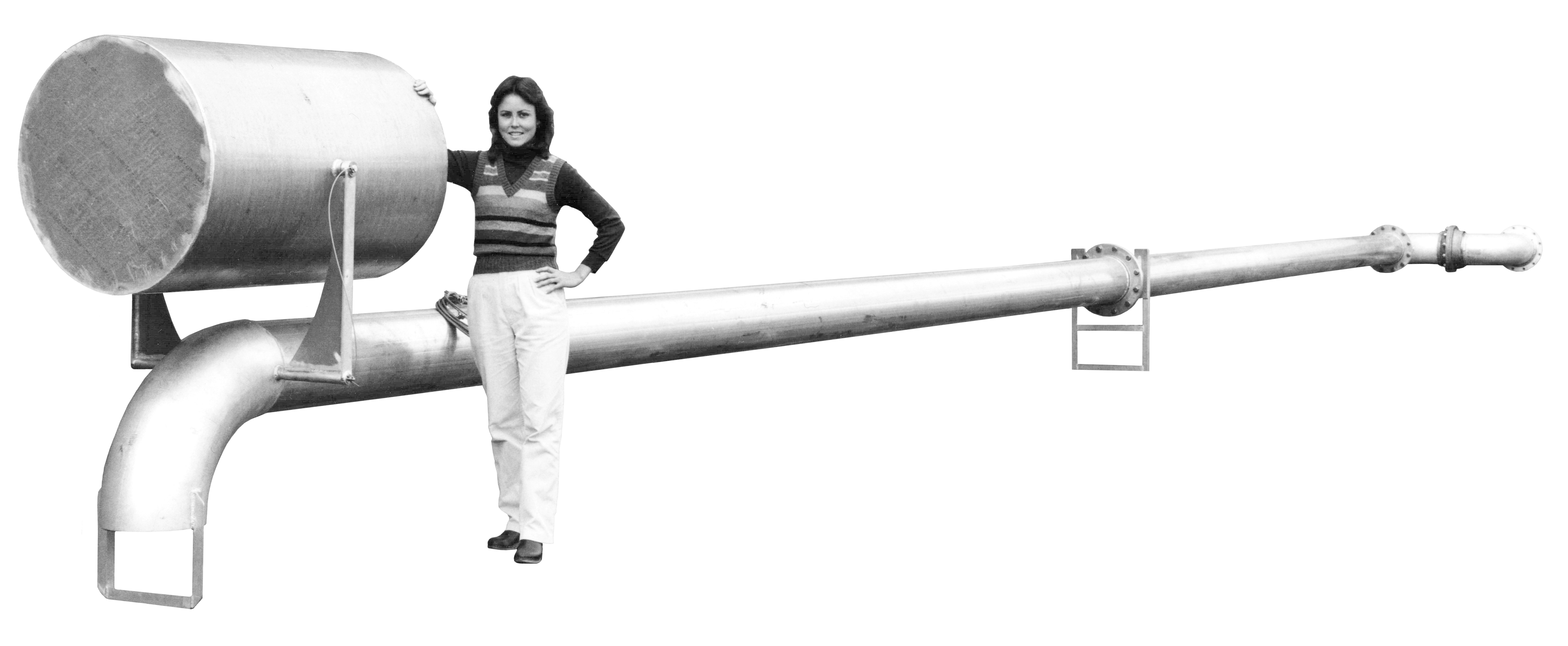
NOTE: Floating suctions cannot be ordered online. Please contact us to get a quote or place an order.


Installation
CAUTION: When installing a floating suction, do not enter the tank until all fuel vapors are cleared.
HORIZONTAL TANKS
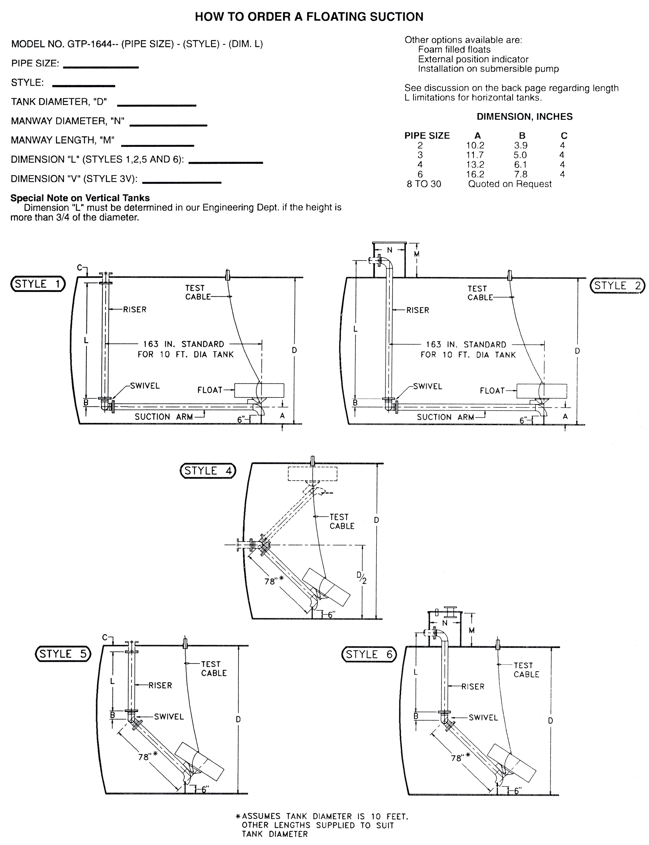
In most cases it will be necessary to remove the float assembly before installation is attempted. This simply requires removal of one stainless steel cotter pin. If an attempt is going to be made to install a floating suction without someone working inside, we recommend Style 5 with the riser flange bolted to a spool piece welded into the cover of the manway. Style 6 is another option. Assembly can be inserted through the manway until the cover comes to rest on the top of the manway. Care must be taken to insure that the swivel turns in the right direction so that the float is located above the suction arm. Also, a special provision must be made for attaching the test cable by threading it through a special port in the manway cover. The minimum manway inside diameter to permit installation of Style 5 without removing the float is shown in the following chart for each size:
| Pipeway Size | Manway Diameter |
|---|---|
| 2″ | 17″ |
| 3″ | 19″ |
| 4″ | 21″ |
| 6″ | 25″ |
This chart does not apply to Styles 1, 2, or 3 because the limiting factor on being able to insert these long suction arms is whether or not the arm will contact the bottom of the tank before it can pass through the manway. We have developed simple charts for each size of floating suction for a wide range of tank diameters, manway diameters, and manway lengths so that we can quickly determine the maximum suction arm length that can be inserted in your tank. This is why you must give us the dimensions of your tank when you place an order. It should be understood that it will be necessary in most instances to remove the float and swivel before installation if Styles 1, 2, or 3 are selected.
SUCTION ARM LENGTH for our standard designs of Styles 1, 2, and 3H is based on the assumption that the fitting in your tank is positioned so that the arm will operate freely without contacting the end of the tank. The customer is expected to inform us if he wants a non-standard suction arm length. We do not recommend allowing the arm to rise to an angle greater than 45°.
TEST CABLE INSTALLATION should be arranged so that the cable will not be bent at a sharp angle when the yardman pulls upward. Ideally, the opening through which the cable is installed should be as close as possible to the point where the center of the float contacts the top of the tank (see typical arrangement for Style 4). The cable may be attached to the lower face of a pipe cap that will close the top of the access port.
All connection flanges for all styles are 150# ANSI-RF unless otherwise specified.
VERTICAL TANKS
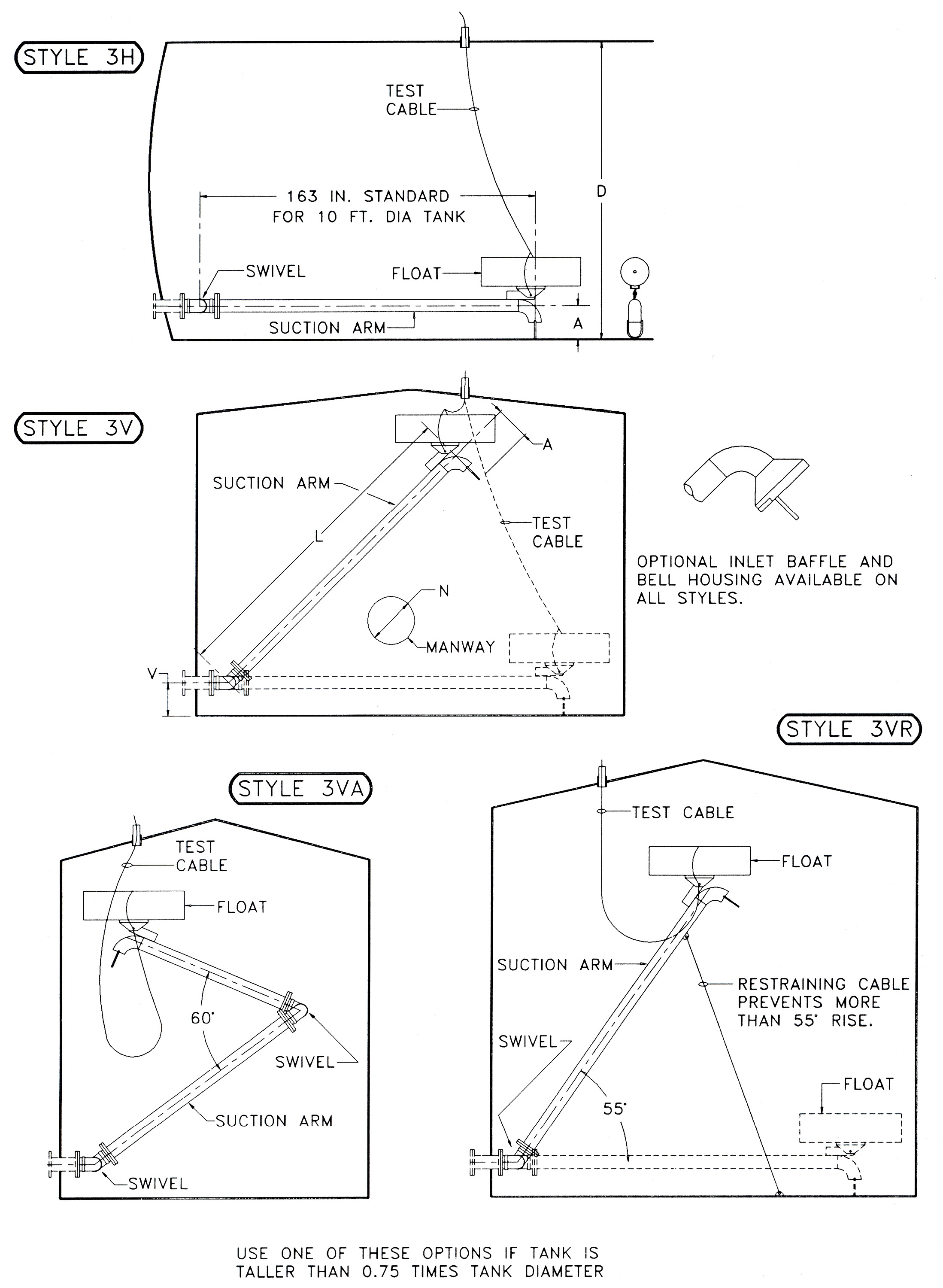
Floating suctions for vertical tanks must be disassembled during installation. The purchase order must specify the manway diameter so that a float can be selected that will pass through. If the arm length/diameter ratio is very great, we add intermediate legs as necessary, especially if the outlet flange is lower than the inlet, causing the arm to remain full when the tank is empty.
If the height of the tank is greater than 75% of the diameter, the arm will rise to such a steep angle that it may hang up. One option is for us to add a restraining cable and let the fuel rise as far above the float as necessary (see Style 3VR). The other option is to add swivel joints and use multiple arms (see style 3VA); we have had to use as many as four in very tall, small-diameter tanks. Special provisions are made to guide the float and arms.
NOTE: We manufacture floating suctions for tanks having floating roofs or pans, but only if we are given drawings of the pan construction so that we can design a track for the rollers.

