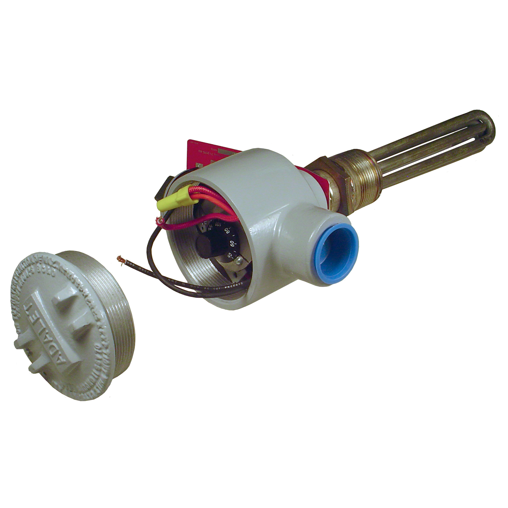
Heaters for Filter Separators
Rated “Explosion Proof” – NEMA 7 Class 1, Groups B/C/D, Division 1
Features:

| Watt Rating | Probe Length (in.) | Thread NPT (in.) | Model No. (standard) | Model No. (with light) |
|---|---|---|---|---|
| 300 | 6.0 | 1 ¼ | GTP-1756 | GTP-1756L |
| 750 | 7.0 | 1 ¼ | GTP-1757 | GTP-1757L |
| 1000 | 9.7 | 1 ¼ | GTP-1758 | GTP-1758L |
| 1500 | 12.5 | 1 ¼ | GTP-1759 | GTP-1759L |
| 300 | 12.5 | 1 | GTP-1760 | GTP-1760L |
| 750 | 18.5 | 1 | GTP-1761 | GTP-1761L |
| 1000 | 24.7 | 1 | GTP-1762 | GTP-1762L |
| 1500 | 38.5 | 1 | GTP-1763 | GTP-1763L |
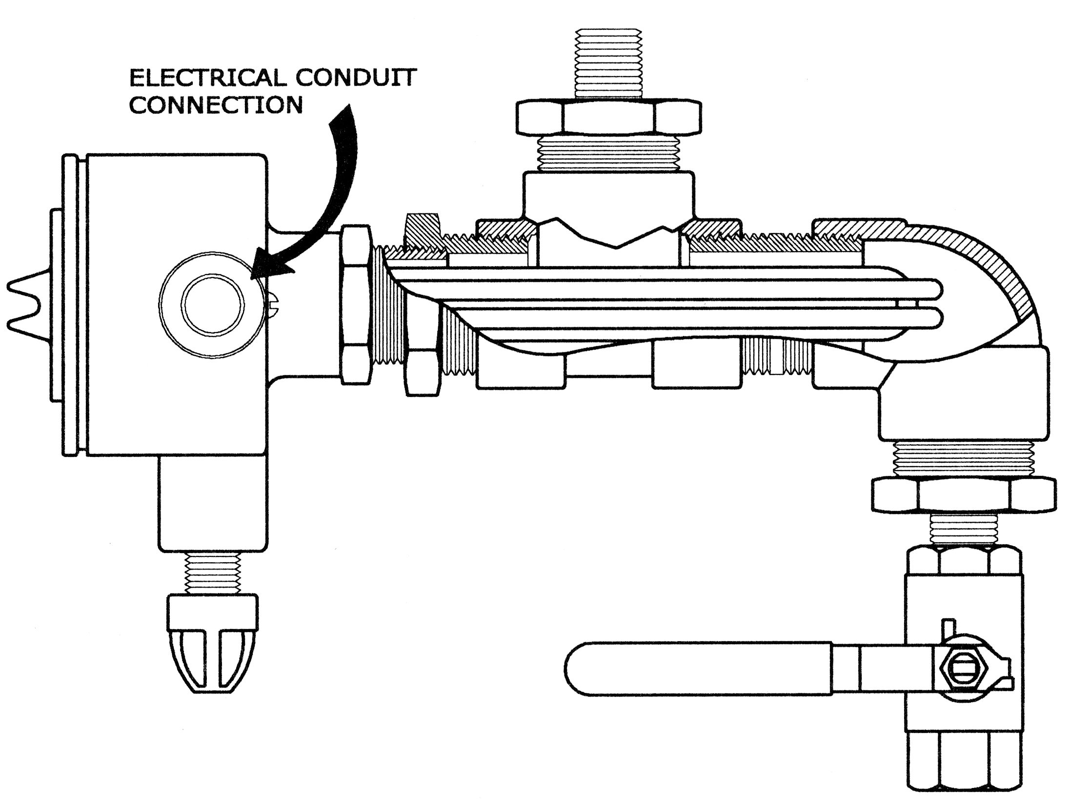
Shown below is the typical pipe and fitting arrangement for a 300 watt heater installation in a drain system. The nipple at the upper left screws into the sump drain valve at the bottom. The optional indicator light is in the foreground. The electrical conduit enters on the opposite side of heater.

General Discussion
Our heaters are made specially for us by a highly qualified manufacturer with many years of experience. The purpose of a heater in a filter separator is to prevent the formation of ice in the water drain system. This makes it possible to drain water that has collected. Attempts have been made in the past to heat the entire filter separator by applying insulation but this has been found to be impractical because there are too many ways that heat can be lost. Furthermore, when insulation has been soaked in rain water, which is nearly impossible to prevent, heat loss is increased and severe corrosion develops.
The usual approach is to have one heater for the sump and a second one for the drain piping. The sump heater should be carefully located so that it is as close as possible to the surface on which water collects. However, it should also cross over the drain port and under the float if a float operated pilot valve is used. If the vessel is exceptionally large, a second sump heater may be installed in the drain piping only.
Most of the heaters covered in this bulletin are used as replacements for heaters that have failed. If you intend to install a heater in a filter separator that was not designed with a proper fitting, be advised that the welding must be done by an ASME qualified shop if the vessel was originally built to Section VII of the ASME code.
The most common failure of a heater is rusting of the steel sheaths. The frequent result of such a failure is that fuel will leak into the electrical housing and it sometimes will fill up the electrical conduit that carries power to the heater. When replacing a heater under such circumstances, we recommend that the conduit be thoroughly dried and new wires installed. The reason for this is that ignition could occur from the arcing of the thermostat. Although a fire in the conduit is “safe,” shorting could occur because of burned insulation.
Notes
- 1
When installing one of our heaters, the thermostat must be adjusted. Remove the cover and note a black dial knob that is calibrated from 40-120°F. Turn this knob until the preferred temperature is set next to the indicating button.
- 2
There are two screws that hold the thermostat. The set point marker is the screw that 60°F can be turned to.
- 3
You can easily check the thermostat for accuracy at any time if you know the temperature of the contents of the filter. Turn off the power first. Then turn the knob slowly from a higher setting. You will note an audible “click” when you read the temperature that causes the thermostat to engage the circuit. If you now turn the knob in the other direction, there will be another “click” when the thermostat disengages. The temperature spread is about 5°F.

