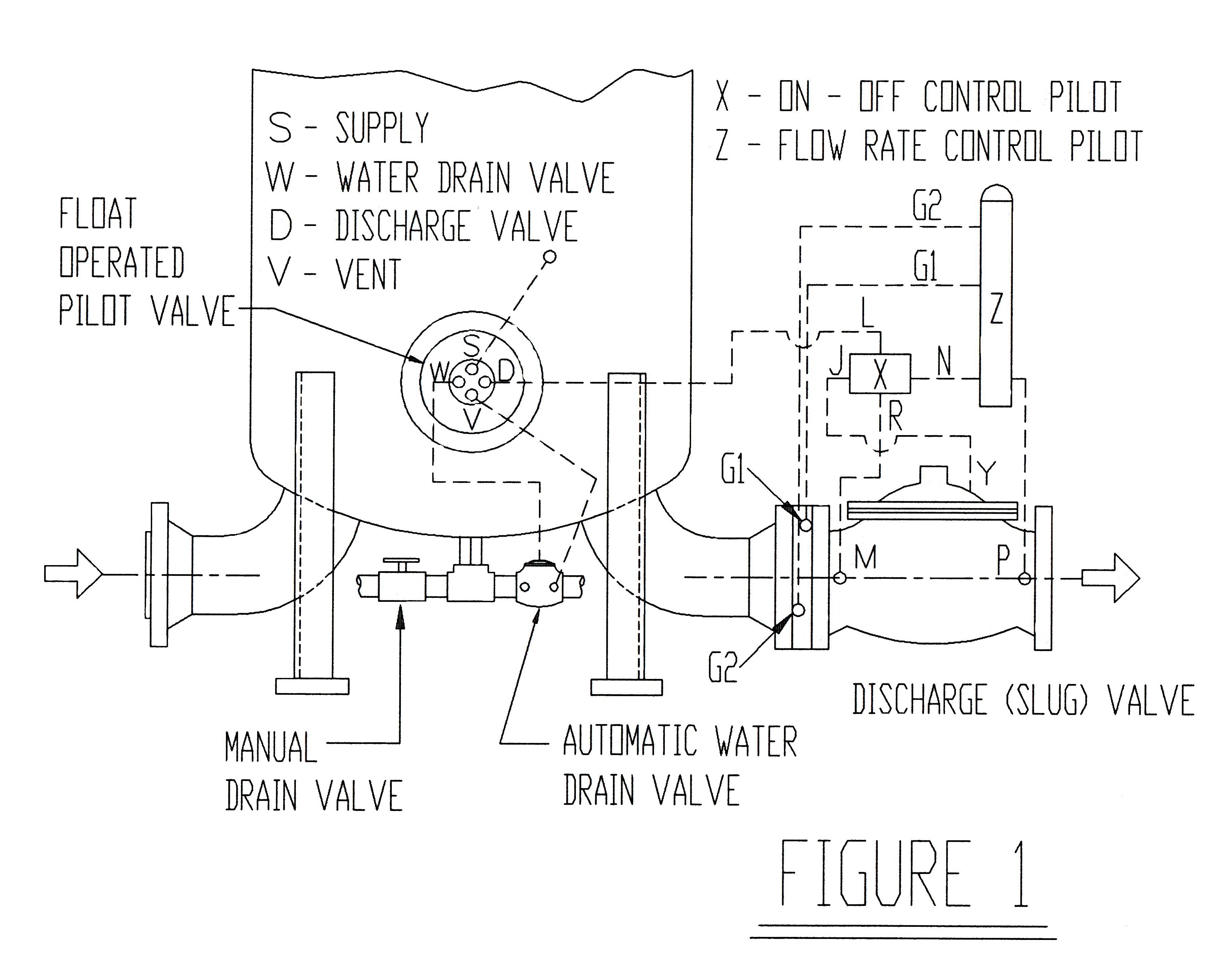
How many people think that a water slug valve will close because it “senses” a slug of water? It is amazing how many people believe this but those of you who read GamGrams 10 and 11, know that the “intelligence” comes from a device called a “FLOAT OPERATED PILOT VALVE” or an electrical device that can sense the difference between water and fuel in the sump of a filter separator.
A very curious thing about slug valves is that people outside of the filter separator business refer to the very same valve as a diaphragm operated control valve. The term “slug” was dreamed up many years ago by filter separator people, because it was necessary to stop flow in a fuel system if a “slug” of water collected in the sump at a rate greater than it could be drained away. A hydraulic signal to the slug valve (also known as the discharge valve) will cause it to close to prevent fuel flow until the water level has been reduced to a safe range.
Sometimes the slug valve is called a RATE OF FLOW CONTROL VALVE. All this means is that it is a slug valve that was modified to perform both functions. It can operate as a slug valve and it can also automatically limit the flow rate to the maximum rating of the filter separator. This is an important optional function because filter separators are very velocity limited. Note: If you want to upgrade your slug valve to control flow rate, we can tell you how to do it, on request.


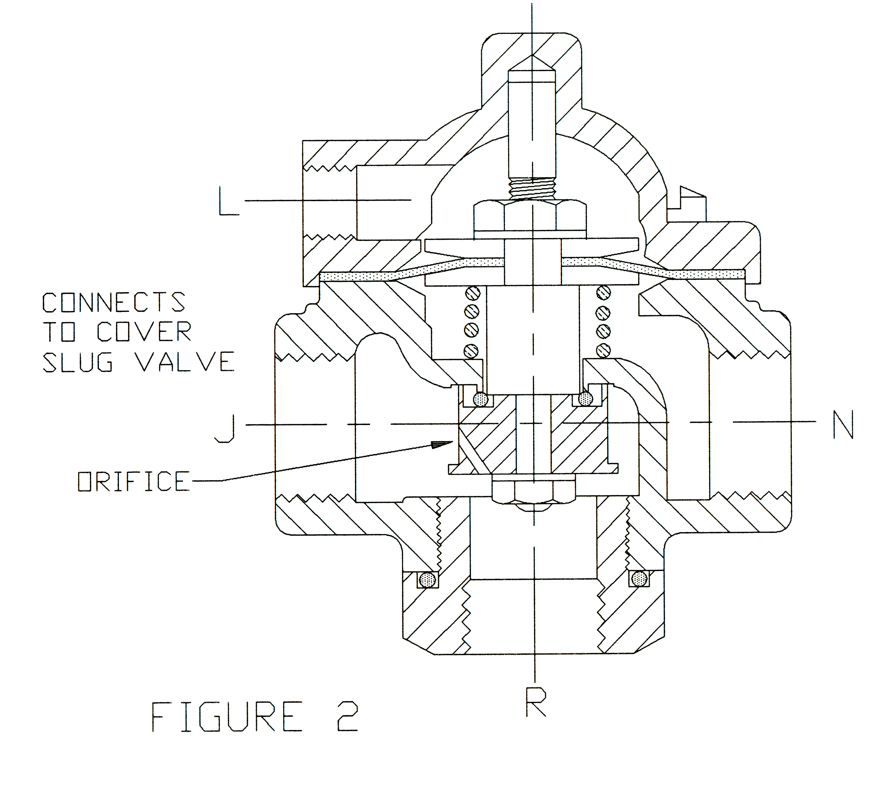
In Fig. 1, there are two pilot valves shown, X and Z. X is an On-Off pilot valve and the other (Z) controls the rate of flow. Watts, Smith and Oil Capital make On-Off pilot valves that are similar. Each requires a pressure signal to cause the slug valve to open. A pilot of this type is shown in Fig. 2 in the closed position. Note that pressure from the supply port M is directed to Y, the cover of the slug valve, to close it. In other words, pressure from M goes through port R, then port J and to port Y on the cover. If control pressure from the float operated pilot valve is applied at port L to open the on-off pilot, the slug valve cover is vented through ports Y, J and N of the on-off pilot into port P. The slug valve then opens because system inlet pressure at M is greater than outlet pressure at P.
The tricky feature in the On-Off pilot is the orifice shown by an arrow. If the on-off pilot has been opened to start main valve flow, the orifice allows a small “pilot flow” from R to bypass the main valve through port N and then to P. When a rate of flow pilot is added, you can see that by regulating or throttling this “pilot flow”’ the pressure at the slug valve cover can be regulated to cause the main valve to modulate between the open and closed positions.

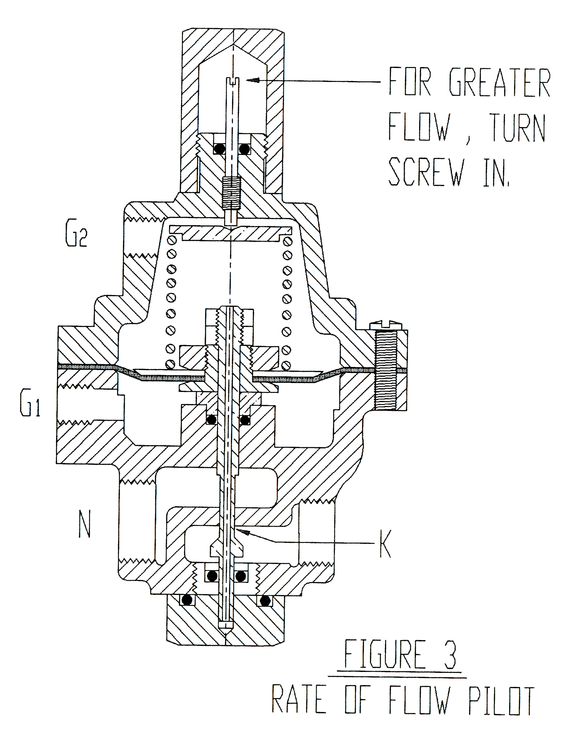
All manufacturers make rate of flow pilots (Fig. 3) that are almost identical. To control it, an orifice plate is located at the inlet of the discharge valve. Pressure taps (G1 and G2) are located at the downstream and upstream sides of the plate which has a hole in it that is somewhat smaller than the piping. G2 is the pressure upstream of the orifice plate while G1 is the pressure after the orifice plate. When flow passes through the orifice, the pressure loss across the plate becomes greater and greater as the flow rate increases. In other words, an orifice plate is a simple flow meter. By taking these two pressures as G2 (high) and G1 (low) to a pilot valve Z, the diaphragm will move away from the side having the highest pressure. This force is resisted by a spring, but the tension on the spring can be changed by turning the screw at the top. This pilot valve will adjust itself to try to maintain a perfect balance but in so doing, it regulates the amount of “pilot” flow that can pass through port K. This will influence the pressure that is in the slug valve cover to modulate flow rate. For example, if the flow through the orifice plate is too high, its pressure drop is also high. This results in a partial closing of port K, restricting pilot flow. This causes more pressure on top of the slug valve diaphragm, causing it to close slightly to correct the excessive flow rate.

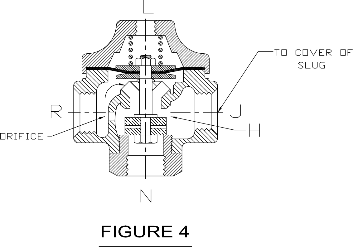
The Cla-Val system is exactly the same, except that the On-Off pilot (Fig. 4) works in the reverse of the one in Figure 2. In the position shown, control pressure is being applied at L. Supply pressure at R goes through J and directly to the slug valve cover through port Y to block fuel flow through the main (slug) valve. To open the slug valve, L must be vented so that pressure at R will lift the diaphragm and close port H. The orifice then supplies “pilot” flow and all other functions are the same as described for other brands. The slug valve cover is vented through port J to N and then to P.
When slug valve problems occur, our experience has been that diaphragm failures are the primary cause. These are easy to find. Disconnect the fitting at Y and turn on the pump. Continuous flow from the slug valve cover means a diaphragm failure. A failure of the On-Off pilot diaphragm in Figure 2 can be detected by disconnecting the fittings at N and L. Apply pressure at N and look for leakage at L. A failure in the rate of flow pilot diaphragm is found by disconnecting one of the orifice pressure fittings, G1, or G2. Leakage indicates failure of the diaphragm.
We have reproduced Tables 2 and 3 from GamGram 10 so that you can follow a typical troubleshooting problem. We cannot review all failure modes for all brands, but this one shows the reasoning technique. You have Cla-Val equipment and the slug valve will not open. Disconnect the fitting at L in Figure 4. If flow comes out of the tube, the float is up so water is in the sump and that is the reason the slug valve will not open. If the automatic water drain valve will not open, its diaphragm may be found to be leaking and water flow will be found in the vent tubing from the float valve. If the On-Off pilot diaphragm had failed, a fuel flow would have been found in the vent before the fitting at L was disconnected.
Table 2
| Port Identification | ClaVal | Watts** | Brooks | Oil Capital | Smith* | |
|---|---|---|---|---|---|---|
| before 5/86 | after 5/86 | |||||
| Supply | S | A | P | D | P | D-9 |
| Water Drain Valve | W | C2 | DV | A | W | A-2 |
| Discharge Valve | F | C1 | SV | C | A | B-5 |
| Vent | D | B | E | B | E | C-6 |
Table 3
| Float Position | ClaVal | Watts⋆ | Brooks | Oil Capital | Smith* | ClaVal CFF12-H3 | |
|---|---|---|---|---|---|---|---|
| before 5/86 | after 5/86 | ||||||
| Up | F-S, W-D | C1-B, C2-A | SV-E, DV-P | C-D, A-B | A-E, W-S | 5-6, 2-9 | F-D, W-S |
| Intermediate | F-D, W-D | C1-A, C2-A | SV-P, DV-P | C-B, A-B | A-S, W-S | 5-9, 2-9 | F-S, W-S |
| Down | F-D, W-S | C1A, C2-B | SV-P, DV-E | C-B, A-D | A-S, W-E | 5-9, 2-6 | F-S, W-D |
In conclusion, we feel that we should have emphasized in GamGrams 10 and 11 that the Supply fuel should be filtered to prevent malfunctions in the float pilot. Supply must come from downstream of the coalescers or be separately filtered. Also, in retrospect, we might have recommended a 40 mesh strainer upstream of the automatic drain valve. Most leaks from that valve are caused by dirt in its seat.

