
Fuel Sampling Kits
Our fuel sampling kits have become the standard in the industry for obtaining test samples of jet fuel. With more than a million in service, they have proved to pay for themselves by saving countless hours of downtime because accurate contamination test results are obtained the first time.
In the past, thousands of work hours have been wasted and fueling facilities have been shut down simply because the sampling tap was contributing dirt during the sampling period. Rusty pipe threads, steel gate valves and collections of reducing bushings that are never subjected to fuel flow, except when a contamination test is to be run, have been found to be a prime cause of poor color results when tests are performed to ASTM D2276. Flushing does not clean normally stagnant steel fittings.
Our probe penetrates through the pipe coupling that is welded to the pipe. There is no possibility of rust and dirt, that usually collects in stagnant pockets (such as welded couplings), reaching the test membrane.
Non-ferrous materials are used in our kits, All passages are small (¼” pipe size) to insure that there will be enough velocity during the flushing cycle to carry away any sediment that may have collected.
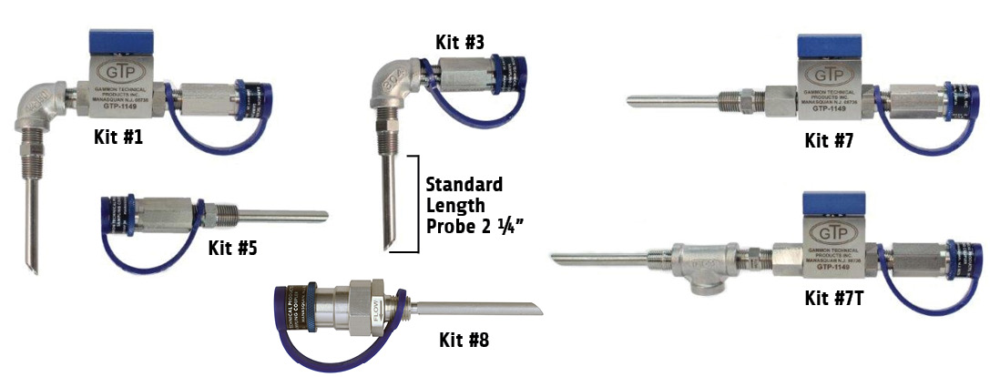
Kit No. 7T allows pressure sensing and sampling independently through one pipe connection. Probe penetrates all the way through the tee. Sample never contacts the tee. Branch on tee is for pressure gauge connection; it senses pressure on the inside of probe tube.
Kit No. 8 features our Self-Flushing QD, which eliminates the need to flush the connection before every test. It will only allow fuel from the center of the pipe to reach the QD. This reduces the amount of time spent and the volume of fuel that has to be handled. For panel mounting, Kit No. 8RM includes Kit 8 plus a remote mount (standard probe sizes only).
The GTP-144 Probe is made to reach the center of a 4” pipe but can be used in any pipe of 2” or more. The threads on the probe are both ¼” NPT male (use reducing bushing to come down to this size). We can also supply special probes of any specified length up to 6”.

Sampling Kit Parts & Accessories


Instructions for Sampling Probe Kits
- INSTALLATION
- Screw the GTP-144 probe in a ¼” NPT female thread using 1½ wraps of PTFE pipe thread sealant as a sealant and thread lube. Use reducing bushings if necessary. Wrap the tape tightly, so that it forms itself into the male thread. Do not let the tape extend beyond the open end of the fitting or fragments of the tape will get into the flow stream. NEVER screw stainless steel threads together without PTFE tape – they will gall.
- Adjust the position of the probe by tightening until the arrow on the flat of the hex is pointing downstream – in the direction of flow in the pipe.
- Install other components of the kit using PTFE pipe thread dope for each connection. Be certain that sample flow is in the correct direction.
- The sampling coupler is supplied with a dust plug that has a lanyard for attachment. Place the lanyard before assembling.
- Screw the GTP-144 probe in a ¼” NPT female thread using 1½ wraps of PTFE pipe thread sealant as a sealant and thread lube. Use reducing bushings if necessary. Wrap the tape tightly, so that it forms itself into the male thread. Do not let the tape extend beyond the open end of the fitting or fragments of the tape will get into the flow stream. NEVER screw stainless steel threads together without PTFE tape – they will gall.
- FLUSHING – A new sampling connection requires extensive flushing. For best results, use the GTP-1110 Bonding and Grounding Hose (see Bulletin 8) to obtain high velocity in the passages of the sampling kit components.
- CONTAMINATION TESTING – Use Gammon MiniMonitor® Kit model GTP-172. Follow detailed instructions for best results. The sampling coupler can be connected without the risk of spraying fuel, if this procedure is followed:
- Slide the collar of the coupler as far as it will go toward its threaded end. Remember, the collar does not open the internal valve.
- Insert the connecting nipple in the open port of the coupler as far as it will go without depressing the internal valve, but continue to hold the collar.
- Then quickly press the nipple straight in with a force of about 25 lbs. and pull the collar back to its original position. This 25 lb. force causes the internal valve to open.
- A dry disconnection can be made simply by depressing the collar.
- Slide the collar of the coupler as far as it will go toward its threaded end. Remember, the collar does not open the internal valve.
See also: GamGram 6.


