About Sandra Gammon

This author has not yet filled in any details.
So far Sandra Gammon has created 135 blog entries.

GamGram 8: Las Especificaciones EI/API que Definen al Filtro Separador

¡Cumplir con especificaciones no es cosa sencilla!

Nos gustaría agradecer a Velcon Filtres por su ayuda en la elaboración de este GamGram.

La especificación EI-1581 se encuentra actualmente en su sexta edición. Este documento solía ser elaborado por el Instituto Americano del petróleo (API), pero ahora está bajo la responsabilidad del Instituto de Energía con sede en Londres y es conocido por las siglas EI. Estas especificaciones son reconocidas en todo el mundo como el No. 1 como guía para la realización del diseño, los ensayos y el rendimiento de elementos filtrantes coalescedores y separadores contenidos en las carcasas conocidas como filtros separadores.

Hay dos condiciones importantes dentro esta especificación que usted se debe cumplir:

  1. Sus filtros separadores deben tener los elementos adecuados en dependencia del tipo de carcasa, el grado y tipo de combustible y al caudal de operaciones de su sistema.
  2. Su carcasa debe tener los accesorios adecuados en perfectas condiciones técnicas para realizar su función.

En este GamGram, trataremos sobre la primera condición la cual ayuda a determinar si usted que tiene los elementos correctos en la carcasa adecuada a las condiciones operacionales y el caudal de su instalación.

Nuestras descripciones a continuación no deben considerarse como una la regla estricta. Por ejemplo, los filtros separadores tipo S-LW no deben ser seleccionados para ser colocados en los sistemas de hidrante donde el agua puede estar presente o no en cantidades significativas, esto sería una selección errónea, además la productividad y el caudal son otros factores a tener en cuenta. Un gabinete de abastecimiento de combustible corporativo pequeño tendrá menos productividad que una instalación de abastecimiento de combustible de una aerolínea.

Categorías

Esta especificación detalla diferentes “Categorías” para la clasificación de los filtros separadores. |debe determinar en cuál de ellas encaja el combustible con que opera su instalación. Esta es tu primera tarea.

Categoría C Corresponde a los usados con combustibles para la aviación comercial (Jet A o Jet A-1) con o sin adicción de aditivos tales como para mejorar la conductividad (SDA) o los inhibidores de la corrosión, mejoradores de la lubricidad (DCI4A).
Categoría M Corresponde a los usados con combustibles para la aviación militar (JP-4, JP-5, JP-8, JP-5/8 ST, NATO F-34, NATO F35) que contienen los aditivos militares básicos que incluye el aditivo anticongelante (FSII, DiEGME o “Prist”), con o sin adicción de aditivos tales como para mejorar la conductividad (SDA) y inhibidores de la corrosión, pero no puede incluir el aditivo para mejorar la estabilidad térmica “+100”
Categoría M100 Corresponde a los usados con combustibles para la aviación militar (JP-4, JP-5, JP-8, JP-5/8 ST, NATO F-34, NATO F35) que contienen el aditivo para mejorar la estabilidad térmica “+100” y además los aditivos militares básicos que incluye en la categoría M.

NOTA: El conjunto de elementos y las carcasas que cumplen con la categoría “M100” no son mejores ni iguales a la categoría “M”. Asegúrese de que el recipiente y los elementos de su filtro sean correctos para la aplicación específica, el combustible y los aditivos para su sistema.

TIPOS

Su segunda tarea es determinar qué tipo de carcasa según la especificación es la correcta para su selección.

Tipo S Corresponde a las carcasas instaladas en lugares donde puede haber cantidades significativas de suciedad y agua. (Terminales de combustible, almacenes pre-aeropuertos y en los depósitos de aeropuerto). Este tipo es similar a la antigua especificación “Clase A” y “B”.Esta prueba se realiza con un 3 % de agua.

NOTA: Los sistemas calificados de tipo S se califican automáticamente para el tipo S-LD y S-LW, por lo que operar un filtro calificado para ese tipo S cubre todas las eventualidades. Una carcasa tipo “S” a menudo será más grande y costosa que una carcasa S-LW.

Tipo S-LW Corresponde a los instalados en lugares donde se espera una cantidad mínima de agua (Equipos abastecedores de combustible: cisterna repostadores, carros de hidrantes y carretillas) Este tipo es similar a la antigua especificación “Clase “C”.La pueba se realiza con un ½ % de agua. En vez del estándar 3 %.

IMPORTANTE: Si se utiliza una carcasa clasificada para una edición antigua, NO es tan simple pues no se trata solo seleccionar los elementos adecuados y colocarlos. Hay un cambio importante en la especificación actual que hace que su carcasa para el filtro separador no cumpla con los requisitos adecuados. Por ejemplo: si el filtro separador es un recipiente con orientación vertical y la placa interior que sostiene los elementos es plana (nos referimos a la placa que está dentro del recipiente) y perfectamente horizontal esa placa no cumple con las nuevas especificaciones porque según estas especificaciones debe tener una caída o inclinación hacia el desagüe o drenaje con el objetivo de eliminar el agua en su totalidad. Si desea utilizar esa carcasa esta tiene que tener cierta inclinación para ayudar al agua a escurrirse hacia el drenaje

Conclusiones

La selección de la carcasa adecuada así como colocar los elementos filtrantes correctos en su interior constituye un proceso sumamente complicado. El simple hecho de colocar cartuchos filtrantes calificados para la 5ta. Edición no significa que esté operando el filtro según los requisitos de la 5ta edición, para menor resultado necesita la ayuda de su compañía como órgano rector para hacer esto bien. Se debe respetar la cadena de responsabilidad, el orden y lugar requerido. Además, recomendamos utilizar como una buena fuente de asesoramiento al fabricante de filtros de combustible de aviación o al distribuidor oficial de su compañía.

Al hacer una orden de nuevos elementos filtrantes para una carcasa existente, proporcione a su proveedor de elementos filtrantes la siguiente información: (Se puede solicitar un formulario a su proveedor que lo haga más fácil el cual registra todo en un solo lugar, hasta el número de la junta):

  1. Modelo, número y marca de la carcasa.
  2. El caudal máximo actual de operaciones de su instalación así como el que tiene la placa de la carcasa.
  3. El número de parte y la cantidad de cada uno que tiene instalado en su carcasa.
  4. La categoría y el tipo de carcasa. Si no tiene esos datos entonces describa su sistema con la posición del filtro y los récords históricos de contenido de agua y partículas.
  5. Los clientes y el tipo al que se le provee el combustible (aviación general, aerolínea o militares)
  6. Tipo de combustible que suministra

Al hacer los cambios de los nuevos elementos o fabricante garantice una hoja de datos de clasificación por similitud que muestre la correspondencia de esos elementos colocados en la carcasa acorde a la categoría y el tipo solicitado No solo se requiere una hoja de datos con los cálculos de similitud para cada recipiente, también, se debe colocar en el recipiente una placa no ferrosa de identificación grabada. Que detalle los siguientes datos, modelo del recipiente, los modelos de elementos instalados y el caudal para el cual está calificado. Al cambiar de una marca a otra también se debe cambiar la placa de identificación. Las etiquetas autoadhesivas no cumplen con los requisitos de la especificación pues se degradan con el tiempo.

Cuando tenga la necesidad de adquirir una carcasa nueva esta debe tener siguiente información:

  1. El caudal máximo operacional de su instalación.
  2. La presión máxima que puede alcanzar el sistema.
  3. La categoría y el tipo de carcasa que se necesita y si tiene dudas describa su sistema, donde se coloca el filtro (carga de carros repostadores, descarga de combustible en un repostador, etc.), el historial de contaminante agua /partículas.
  4. La orientación de preferencia horizontal o vertical (cada tipo tiene sus ventajas y desventajas).

GamGram 8: Las Especificaciones EI/API que Definen al Filtro Separador2024-12-26T16:46:12+00:00

GamGram 8: EI/API 1581 Filter Separator Specifications

Meeting the specification is not simple!

We would like to thank Velcon Filters for their help with this GamGram.

The EI-1581 specification is currently in its 5th edition. This used to be an API document, but is now under the EI, the London-based Energy Institute. It is recognized around the world as the #1 document for the design, testing and performance of Filter Separator vessels and the filter coalescer elements/cartridges/separators that go into them.

There are two important elements of this specification for you to comply with:

  1. Your filter separators have the correct elements for the vessel type, fuel and configuration at the flow rate at which you operate them.
  2. You have the correct accessories in proper working condition on your filter separators.

In this GamGram, we will address the first element, determining that you have the correct elements in the correct vessel for the conditions and flow rate of your facility.

Our descriptions below are not to be considered the rule. For example, in a hydrant system where water is, or can be, present on occasion in significant quantities, Type S-LW filter separators are not the correct choice. Throughput and flow rate are other factors. A small corporate fueling cabinet will see less throughput than an airline fueling facility.

Categories

There are different “Categories” in this specification. Determining which one you fit into is your first task.

Category C For commercial Jet Fuel (Jet A or Jet A-1) with or without certain additives such as conductivity improver (SDA) and CI/LI (DCI4A, corrosion inhibitor/lubricity improver).
Category M For Military Jet Fuel (JP-4, JP-5, JP-8, JP-5/8 ST, NATO F-34, NATO F35) that contains the basic military additives, including Anti-Icing Additive (FSII, DiEGME or “Prist”), SDA and Corrosion Inhibitor, but NOT “+100” thermal stability improver additive.
Category M100 For Military Jet Fuel that contains “+100” type of additive, meant to improve the thermal stability of the fuel in the aircraft. This fuel may also contain the additives in category “M”, above.

NOTE: Element and vessel sets meeting category M100 are not better or equal to category “M”. Be sure that if your filter vessel and elements are correct for the specific application, fuel and additives for your system.

Types

Your second task is to determine which type in the specification is correct for you.

Type S For locations such as fuel terminals or airport fuel depots. In such locations, significant amounts of dirt and water may be present. This is similar to the old “Class A” and “B” specification; this test is run at 3% water.

NOTE: Type S qualified systems are automatically qualified for type S-LD and S-LW so operating a vessel qualified to type S covers for all eventualities. But a type S vessel will often be larger and more expensive than a S-LW vessel.

Type S-LW For locations are on refueler trucks or hydrant carts, where minimal amounts of water are expected. This is similar to the old “Class C” specification; this test is run at ½% water, not the standard 3%.

IMPORTANT: If you are fitting elements into existing vessels, it is NOT as simple as getting the correct elements. There is an important change in the specification that may make your present filter separator vessel non-compliant. If your filter separator is a vertical vessel and it has a flat deck plate (inside the vessel looking down, a plate that is perfectly horizontal and is welded all the way around the inside of the vessel to the vessel shell, with or without a “sump”) that deck plate must be sloped towards the drain to remove all water. You cannot meet the specification using this vessel or get around this specification improvement by tilting your vessel.

Conclusions

Choosing the correct vessel and then putting the correct elements in it is more complicated than ever before. Simply fitting 5th qualified cartridges does not mean that you are operating the vessel to 5th edition requirements. You need to have your company’s help in doing this right. Follow the chain of responsibility. Additionally your trusted aviation fuel filter manufacturer, or the official distributor, would be a good source of advice.

When ordering new elements for an existing vessel, provide your filter supplier with the following information: (You can also request a form from your supplier which makes this easier, and records everything in one place, right down to the gasket number).

  1. Vessel Model Number and brand.
  2. The maximum actual flow rate the vessel sees in service as well as the flow rate on the name plate.
  3. The part number and quantity of elements you presently have in the vessel.
  4. EI Category and Type — If unsure, describe your system, the position of the filter in the system and dirt/water experience.
  5. Customer types to whom you provide fuel (general aviation, airline or military)
  6. Fuel type – in addition to selecting Category and Type above.

Be sure that you get a Similarity Data Sheet showing the qualification of those elements in that vessel to the Category and Type you requested. Not only is a similarity data sheet required for every single vessel but a non-ferrous engraved nameplate detailing the vessel model, installed element models and qualified flow rate must be affixed to the vessel. Changing from one brand to another means changing the nameplate in order to be compliant. Self-adhesive labels do not meet the requirements of the specification.

When buying a new vessel, provide the following information:

  1. The maximum actual flow rate the vessel will see in service.
  2. Maximum operating pressure of the system.
  3. EI Category and Type – If unsure, describe your system and dirt/water location i.e. fuel depot receipt or loading or a truck mounted into-plane application.
  4. Vertical or horizontal design preference (Both have advantages and disadvantages).

GamGram 8: EI/API 1581 Filter Separator Specifications2024-12-26T16:45:48+00:00

GamGram 7: Las Chispas en el Combustible Jet

Si eres de las personas que al leer el titulo piensas: “No voy a leer este boletín porque siempre conecto todo mi equipamiento a tierra”, Precisamente a ti querido, AMIGO, es precisamente a la persona que queremos llegar antes de que mates a alguien. Vuelve a leer el título. “Chispas en el combustible para aviones”. No estamos hablando de cargas estáticas en las tuberías, camiones o cualquier otro objeto. Estamos hablando de cargas electrostáticas surgidas en el combustible.

Se han escrito varios volúmenes y montones de artículos técnicos muy complejos sobre este tema, pero este boletín es un esfuerzo pionero para evadir los tecnicismos. ¿Alguna vez has notado que cuanto mayor es el número de palabras científicas que se escriben sobre un tema determinado, realmente se entiende menos el problema? Eso es precisamente lo que ocurre con el fenómeno de las cargas electroestáticas en el combustible para aviones.

Queremos dar una reseña de cómo es que se producen las cargas y descargas electrostáticas en el combustible, explicando que la causa de ello es que este fenómeno natural se manifiesta al rozarse mutuamente las moléculas entre sí y entonces se separan potenciales de carga. En otras palabras, es causada por la fricción, precisamente a consecuencias de este roce entre las moléculas. Cuanto más vigoroso sea el roce, mayor será la carga. Los científicos llaman a esto “división de carga”, cuando las “cargas positivas (+) ” se separan de las “cargas negativas (-)” tienes entonces una división de potencial. Aquí es cuando ocurre la separación desigual de electrones o superficies de contacto dejando de ser neutra, Por otro lado, la carga estática se va acumulando, haciéndose más y más grande a medida que se agitan más moléculas en un volumen dado. Si el potencial de carga acumulado en la pared de la tubería o del tanque, se conectan a tierra se estará disipando de inmediato esta carga por lo que no habrá ningún peligro; todo el problema consiste en que las cargas no pueden desplazarse tan fácilmente a través de algunos combustibles y disiparse a “tierra”, este tipo de combustibles se denominan combustibles de “baja conductividad”. ¡POSIBLEMENTE SEA SU CASO!

En todos nuestros sistemas de trasiego y entrega de combustible hay un equipamiento que es el campeón en cuanto a generación de carga estática se refiere y ese no es otro que las “carcasas filtrantes”. La salpicadura creada al llenar los tanques y cisternas, o el torbellino creado por la agitación del combustible al ser bombeado y la rotación de metros contadores, origina el desarrollo de carga estática, pero dentro del filtro es el lugar donde ocurre el mayor ” rozamiento de moléculas y por ende la separación de cargas “, cuanto más fino sea el filtrado, mayor es la carga que se origina, de la misma manera ocurre al la taza de flujo que pasa a través de la carcasa, se incrementara la acumulación de carga estática. Si un vendedor de filtros trata de decirle que sus productos no causan electricidad estática, sáquelo entonces de su vista. Pues estará mintiendo.

Estudios recientes han demostrado que los elementos filtrantes separadores revestidos con teflón generan niveles de carga más bajos que los separadores de papel, es lógico pues hay menos fricción en la pantalla de teflón con agujeros de 74 micrones (μ) que en los separadores de papel donde el flujo tiene un camino más tortuoso con canales de 5 micrones donde la fricción es mucho mayor.

Ahora volviendo a la manera de pensar del lector del primer párrafo el cual intento no leer este boletín por el hecho de que tiene “aterrado” todos los equipos dando por sentado que no tendría problemas. Obviamente, si su combustible tiene una conductividad alta, las cargas se trasladarán a través del dirigiéndose los componentes metálicos conectados a tierra y por ello se disiparán. Pero si su combustible es de baja conductividad, entonces las cargas tardan un tiempo mayor en trasladarse a tierra y disiparse por lo que ese combustible se mantendrá cargado y al ser dispensado a un recipiente puede saltar una chispa un desde la superficie de este combustible hacia un objeto conectado a tierra. Las pruebas han demostrado que la situación más peligrosa ocurre cuando hay un objeto aislado en el espacio gaseoso del tanque, este objeto, actuara como un condesado acumulando la carga, y saltando la chispa ZAP. ¿Necesitamos explicar qué sucede si existe una atmosfera inflamable con concentración de vapor de combustible en presencia de suficiente energía calórica es decir una chispa?

¿Qué Debemos Hacer?

Una “regla general” que la mayoría de los técnicos parecen aceptar es mantener el combustible un tiempo en reposo después de que esta haya pasado por el filtro, ya sea en un tramo de tubería que contenga el volumen adecuado o en un recipiente a presión por un periodo mínimo durante 30 segundos antes de ser despachado en una cisterna o tanque abierto. Este período se denomina “tiempo de relajación” que es el tiempo que le tomara para disiparse las cargas acumuladas producto de la filtración. La teoría explica que incluso si el combustible tiene una conductividad, pobre ese tiempo bastara para que las cargas positivas y negativas se habrán anulado entre sí o habrán migrado a una superficie conectada a tierra. Algunas empresas abogan por el uso de aditivos “antiestáticos” para evitar la necesidad de emplear un tiempo extra para la relajación. Sin embargo, la palabra “antiestático” es un término que no es correcto pues debería llamarlo aditivo para mejorar o aumentar la conductividad del combustible.

Si está operando su instalación con un combustible que no tiene adicionado aditivo antiestático para mejorar la conductividad del mismo, todo lo que tiene que hacer es echar un vistazo a la instalación y comprobar que el combustible una vez le sale de la carcasa filtrante al pasar aguas arriba debe tener como mínimo 30 segundos de estanqueidad (tiempo de relajación). Desearíamos contar un equipo o calibre que pudiera indicarle este tiempo, pero al no tener uno, hemos elaborado un método furtivo y no científico utilizando aritmética simple. Que le mostramos a continuación

Ejemplo 1:

Ejemplo 2:

Si usted es de lo que ama las fórmulas matemáticas reales entonces utilice la siguiente:

C = 0.0408 x (L1D12 + L2D22 + L3D32 + etc.)

Donde “C” es la capacidad en galones del tramo de tubería (como el paso 2), “L” es la longitud del tramo, y “D” es la sección o diámetro de la tubería. 0.034 -es la constante para el cálculo en galones americanos (0.034 seria para galones imperiales y 0,5067 para litros).

Finalmente:

Si al hacer los cálculos se da cuenta que su sistema no tiene suficiente espacio para otorgarle al combustible que sale del filtro un tiempo de relajación de 30 segundos con mucho gusto le mostramos dos alternativas:

  1. Reduzca el Flujo de su sistema.
  2. Haga un rediseño de su sistema.

Si su sistema no cumple esa condición,

NUNCA DIGA QUE

su sistema es lo sufímente seguro porque nunca ha tenido una explosión, pues sencillamente están dadas todas las condiciones para ello.

GamGram 7: Las Chispas en el Combustible Jet2024-12-26T16:45:07+00:00

GamGram 7: Sparks from Jet Fuel

If you are already saying to yourself, “I’m not going to read this because I always ground everything,” YOU, FRIEND, are the person we want to reach before you kill someone. Read the title again. Sparks FROM jet fuel. We are not talking about static charges on pipes, trucks, or any object. We are talking about electrostatic charges IN fuel.

Volumes and heaps of deep technical papers have been written on this subject but this article is a pioneering effort toward the non-technical. Have you ever noticed that the greater the number of scientific words that are written on a subject, the less the problem is really understood? That is the situation with static charges in jet fuel.

We like to describe how electrostatic charges build up in fuel by explaining that it is caused by rubbing molecules together. In other words, it is caused by friction — friction between molecules. The more vigorous the rubbing, the greater the charge becomes. The scientists call this “charge separations”. In other words, when the “pluses” separate from the “minuses” you have charge separation. This is when charge separation occurs. Also, the charge becomes bigger and bigger as more of the molecules in a given volume are agitated. If the charges move to the wall of the pipe or tank, they are immediately grounded and can cause no hazard; the whole problem is that the charges cannot easily move through some fuels to a “ground”: these are called “low conductivity” fuels. POSSIBLY YOURS!

There is one item of equipment that is clearly the champion of all static charge generators — a filter. The agitation created by splash loading or by pumps, piping, valves, and meters causes a charge to develop, but the filter is the place where the most “molecule separation” occurs — and the finer the filter, the greater the charge – and the higher the rate of flow through the filter, the greater the charge. If a filter salesman tries to tell you that his filters do not cause any static, throw him out. However, recent studies have demonstrated that Teflon coated separator elements generate lower charge levels than paper separators. It seems logical that there is less friction and charge separation caused by a 74 micrometer screen separator than by a tortuous flow path in a 5 micrometer paper.

Now we should return to the reader in the first paragraph who threatened not to read this issue because he “grounds everything.” Obviously, if his fuel always has a high conductivity, the charges will move to grounded metal components. But if he has a fuel with a low conductivity, the charges take a period of time to move to ground. If this “charged” fuel is dispensed into a tank, a spark may jump from the surface of the fuel to a grounded object but tests have proven that the most dangerous situation occurs when there is an unbonded object in the vapor space — it acts like a capacitor – it stores up charges – then ZAP. Need we explain what happens if the right amount of fuel vapor is in the path of the spark?

What to Do

A “rule of thumb” that most technical people seem to accept is to keep the fuel in piping or a pressure vessel for 30 seconds after filtering before dispensing it into an open tank. This period is called “system relaxation time.” The theory is that even if the fuel has low conductivity the positive and negative charges will have canceled one another out or have migrated to a grounded surface in that time. Some companies advocate the use of “anti-static” additives to avoid the need for relaxation time. However, the word “anti-static” is a very bad term. It should be called a conductivity improver.

So now if you do not use the additive, all you have to do is take a look at your filter installation to see if you have 30 seconds relaxation time! We wish we had a little gauge to sell to measure this for you but lacking one, we have worked out a sneaky, non-scientific method using simple arithmetic.

Example 1:

Example 2:

If you like real formulas, use this one:

C = 0.0408 x (L1D12 + L2D22 + L3D32 + etc.)

Where C is capacity in gallons, (as in Step 2) L is pipe section length, and D is pipe section diameter. The constant is 0.034 if using Imperial gallons. It is 0.5067 for liter calculations.

Finale:

If you found from your calculations that you did not have enough system relaxation time, we cheerfully offer two alternatives:

  1. Reduce flow rate
  2. Have the system redesigned

DO NOT SAY

“My system must be safe because we have never had an explosion.”

GamGram 7: Sparks from Jet Fuel2024-12-26T16:44:42+00:00

GamGram 6: Anatomía de una Conexión para Muestreo

¡¡Sucedió DE NUEVO!! ¿Porqué es que la gente no lee nuestras instrucciones de instalación antes de instalar nuestros kits para muestreo? El propósito de una sonda de muestreo y algunas partes de acero inoxidable algo costosas con una conexión rápida es para asegurar que una prueba con membrana filtro se correrá en el combustible cuando este fluye por toda la tubería. Las compañías petroleras, aerolíneas, los militares y los contratistas para abastecimiento saben por experiencia que Ud. no puede correr una prueba significativa en combustible que está estancado en la conexión de un ramal. ¿Porqué es que algunos recurren a un contratista sin experiencia en combustibles de aviación que instala una sonda para prueba de manera que se verificará al combustible en una TRAMPA DE SUCIEDAD?

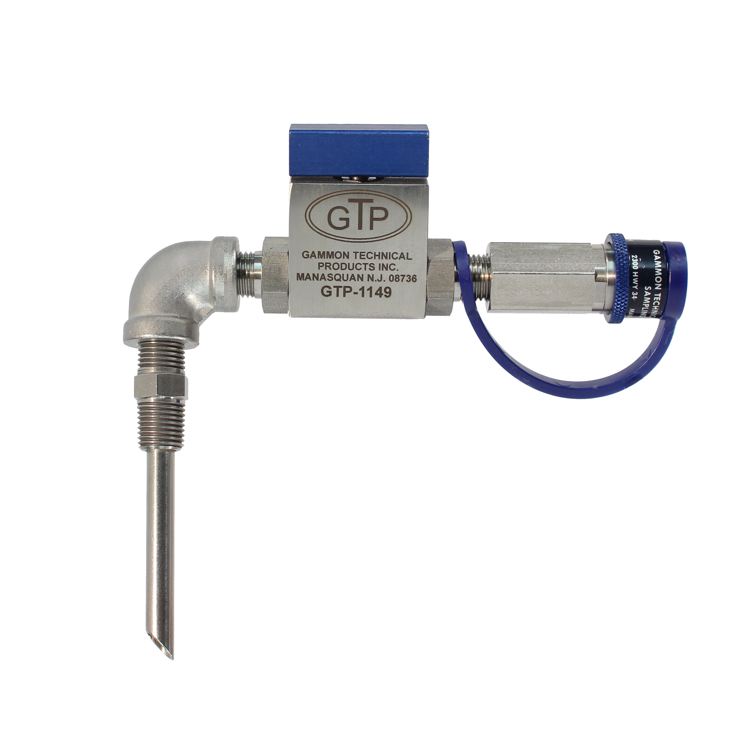
Una vez visité una zona de almacenamiento de un aeropuerto donde encontré exactamente la situación descrita arriba. Una aerolínea había especificado nuestro Kit No. 1 (Ver Figura 1). Todas las partes fueron ensambladas correctamente pero la sonda estaba retirada por lo menos a 6″ de la corriente que fluía porque había sido colocada en una “T” de un ramal de 8″ sin uso. Habían gastado sobre $600.00 USD por lo menos en un ocasión al reemplazar los elementos del filtro separador porque las partículas de suciedad en la membrana filtro indujeron al personal operador a creer que algo estaba mal. ¡Y por favor no argumente que ellos no circularon apropiadamente antes de correr la prueba! En tal situación, Ud. tendría que circular cientos de galones antes de que el combustible en una conexión de un ramal se volviera representativo de la corriente principal.

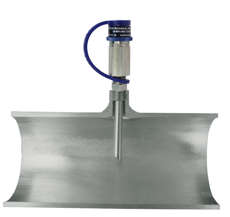
El propósito real de nuestra sonda de prueba es para asegurar que la prueba con membrana filtro se corre en el tipo de combustible que está circulando por la tubería. La sonda (Ver Figura 2) penetrará por cualquier buje reductor así como por el cople soldado a la tubería.

FIGURA 1

FIGURA 2

En el arreglo mostrado en la Figura 1, el combustible que llega a la membrana nunca está en contacto con acero al carbón desde el momento que deja la corriente principal. El recorrido total del flujo hasta la membrana es acero inoxidable liso y el diámetro es pequeño de manera que se puede obtener una buena velocidad durante la circulación para eliminar cualesquier residuo o partícula atrapados.
¿Recuerda Ud. la discusión acerca de velocidad en el GamGram No. 4, “Anatomía de una Tubería para Turbo Combustible”? ¿No es aún más importante poder limpiar una conexión para muestreo? Esto es porqué hemos propugnado por 35 años que la manguera para lavado se use antes de correr la prueba con membrana filtro. Cada vez que se ha embarcado un MiniMonitor Kit ha sido equipado con una de manera que la velocidad de lavado será más de 10 pies por segundo en vez de aproximadamente 0.9 pie por segundo que la válvula para lavado del pequeño MiniMonitor (o la que fabrica Millipore Corp.) permite a 50 psi. Vea Model GTP-1110 en el Boletín No. 8.

HAGA ESTO

Inspeccione sus conexiones para muestreo y conteste las preguntas siguientes:

  • ¿Está ubicado el acceso de manera que pueda Ud. muestrear la corriente principal?
  • ¿Es el acceso de la tubería lo suficientemente pequeño de manera que realmente pueda limpiarlo con el chorro? Si no, una sonda resolverá el problema.
  • ¿Hay una colección de bujes reductores de acero al carbón, codos o coples antes de que el combustible pueda alcanzar esa bella conexión rápida de acero inoxidable? Si así es, ¿usaría también una vieja y herrumbrosa conexión rápida? ¡Ciertamente no! Utilice uno de nuestros Kits para muestreo.
  • PIENSE – ¿Ha corrido alguna vez pruebas con membrana filtro en el lado corriente arriba de su filtro separador de manera que pueda comparar resultados con la prueba corriente abajo? ¿No sería esta la manera lógica de satisfacerse a si mismo en cuanto a que los elementos son actualmente capaces de remover contaminantes?

Esto nos pone en una de nuestras filosofías favoritas. ¿Puede Ud. sentirse seguro solamente porque no encontró suciedad o agua corriente abajo de un filtro separador? ¡Ud. no se sentirá seguro! ¡Ud. puede tener combustible limpio, seco pasando por él! ¿Que seguridad tiene de que el filtro está actualmente en buena condición? Yo, por mi mismo, me sentiría mucho más feliz cuando se encuentra poca agua y suciedad en la entrada si las pruebas corriente abajo muestran que el filtro removió la contaminación. Cuando termino una prueba, me gusta poder palmear la tapa del filtro y decir, “Viejo amigo, estás haciendo tu trabajo.”

GamGram 6: Anatomía de una Conexión para Muestreo2024-12-26T16:44:06+00:00

GamGram 6: Anatomy of a Sampling Connection

It happened AGAIN!!! Why is it that people don’t read our installation instructions before they install our sampling kits? The purpose of a sampling probe and some expensive stainless steel parts with a quick disconnect is to insure that a filter membrane test will be run on fuel as it flows through the pipe. The oil companies, airlines, the military and fueling contractors know from experience that you cannot run a meaningful test on fuel that is stagnated in a branch connection. Why is it that someone hires a contractor with no aviation fuel experience who installs a sampling probe so it will test the fuel in a DIRT TRAP?

I once visited an airport fuel farm where I found the exact situation described above. An airline had specified our Kit No. 1 (See Figure 1). All of the parts were assembled correctly but the probe was at least 6” away from the flow stream because it had been located in an unused branch of an 8” pipe tee. Over $600.00 had been spent on at least one occasion to replace the elements in the filter separator because the dirt particles on the filter membrane led the operating personnel to believe that something was wrong. And please don’t argue that they must not have flushed properly before running the test! In such a situation, you might have to flush hundreds of gallons before the fuel in a branch connection becomes representative of the main flow stream.

The real purpose of our sampling probe is to make sure that the filter membrane test is run on the kind of fuel that is going through the pipe. The probe (See Figure 2) should penetrate through any reducing bushings as well as the coupling that is welded to the pipe.

FIGURE 1

FIGURE 2

In the pictured arrangement of Figure 1, the fuel that reaches the membrane never is in contact with carbon steel from the moment it leaves the flow stream. The entire flow path to the membrane is smooth stainless steel and the diameter is small so that a good velocity can be attained during flushing to carry away any residue or trapped particles.

Do you recall the discussion about velocity in GamGram No. 4, “Anatomy of a Jet Fuel Pipe”? Isn’t it even more important to be able to flush a sampling connection? This is why we have been advocating for 35 years that a flushing hose be used before running the filter membrane test. Every MiniMonitor Kit that has ever been shipped has been equipped with one so that the flushing velocity will be more than 10 feet per second instead of about 0.9 feet per second that the little MiniMonitor flushing valve (or the one made by Millipore Corp.) permits at 50 psi. See Model GTP-1110 in Bulletin No. 8.

DO THIS

Inspect your sampling connections and answer these questions:

  • Is the fitting located so you can sample the main flow stream?
  • Is the fitting on the pipe small enough so that you can really flush it clean? If not, a probe will solve the problem.
  • Is there a collection of carbon steel reducing bushings, elbows or couplings before the fuel can reach that beautiful stainless steel quick disconnect? If so, would you use a rusty old quick disconnect also? Certainly not! Use one of our Sampling Kits.
  • THINK – Do you ever run filter membrane tests on the upstream side of your filter separator so that you can compare results from the downstream test? Wouldn’t this be the logical way to satisfy yourself that the elements are actually capable of removing contaminants?

This puts us into one of our favorite philosophies. Can you feel safe just because you found no dirt or water downstream of a filter separator? You should not feel safe! You could have clean, dry fuel going into it! What assurance do you have that the filter is actually in good condition? I, for one, feel much happier when a little dirt and water is known to be in the inlet if the downstream tests show that the filter removed the contamination. When I finish a test, I like to be able to pat a filter on its dome and say, “You’re doing your job, old friend.”

GamGram 6: Anatomy of a Sampling Connection2024-12-26T16:43:20+00:00

GamGram 5: 集水槽 (沉淀槽) – 第三部

If I had a dollar for every time that a customer has told me, “There is no water in my filter separator sump,” I would be very wealthy. I would be almost as wealthy if I had a dollar for every time I found water in a sump that had just been given its “daily drain.”

如果每次有客户告诉我“我们的过滤分离器的集水槽(沉淀槽)内没有水分”,我可以得到一美元,那么我会非常富有的。同样,如果每次我在一个刚刚完成“每日排放”的集水槽(沉淀槽)内发现水,我都能得到一美元,那我就几乎也会一样富有了。

Why is it that one man can find no water but another man can? Obviously, it’s all in the way you do it.

为什么一个人找不到水,而另一个人可以呢?显然,这一切都与做这件事的方式有关。

The difficulty is that the area where the sump drain is located is usually flat. Water collects on the flat surface but it tends to lie in a “heap” until something happens to break the interface. Watch how water acts in a nearly flat-bottomed wash basin. Water lies on the surface for long periods of time when the water valve is turned off. If you touch it with your finger, at the edge of the drain hole, it suddenly begins to flow into the drain. (We strongly recommend doing this experiment in private, away from those who may not understand scientific studies).

问题在于集水槽(沉淀槽)内的排水管连接所在的区域通常是平的,水会聚集在平表面上,但它往往是处于“堆积”状态,直到发生在某些情况打破界面。观察水在几乎平底的盆中是如何作用的。当水阀关闭时,水会长时间停留在平面上。如果你在排水孔的边缘用手指触摸它,水突然开始流入排水管。(我们强烈建议私下进行这个实验,远离那些可能不了解科学研究的人)。

Most filter sump draining seems to be done by cracking open the drain valve and collecting a pint or two. This does not disturb the layer of water enough to break its surface tension and so the water stays on the flat deck.

大多数过滤器集水槽(沉淀槽)的水排放似乎是通过打开排水阀并收集一两品脱(一品脱约473ml)来完成的。这不会对水层造成足够的干扰,从而破坏其表面张力,因此水会停留在平坦的底面上。

If you really want to do a proper job, you must get some velocity down the drain hole and the best way to do this is to turn on the pump to get pressure. Then open the drain valve as far as possible (without giving yourself a kerosene bath) and collect a couple of gallons in a white bucket.

如果你真的想正确地做好水排放工作,你必须以一定的速度进行排放,最好的方法是打开泵来获得压力。然后尽可能地打开排水阀(当然不要给自己洗航煤浴),然后用一个白色桶中收集几加仑。

I’ll never forget how I learned this trick. One of the real old-timers in jet fuel met me at an airport where a severe surfactant problem had been found. I sumped the filter separator in the conventional way and got a nice clear bucket of fuel. After a few very critical remarks, he used the method described above and collected a sickening bunch of slime, water and crud with the fuel. (I wonder if T.C. remembers this episode?)

我永远不会忘记我是怎么学会这个技巧的。一位航油的老前辈在机场接我,在那里发现了严重表面活性剂问题。我用传统的方法对过滤分离器进行排放,得到了一桶干净的燃油。老前辈在几句严厉的批评之后,他使用了上述方法收集了一堆令人作呕的黏液、水和污垢的燃料。(我想知道TC是否还记得这一幕?)

A doctor can see inside the human body only by looking in your eyes. He uses a bright light and a special glass. Doctors learn many things about your general health this way. The best method we have to learn about the “health” of fuels is to study the water sump.

医生只有通过眼睛才能观察到人体内部结构。他需要用明亮的灯光和特殊的镜子。医生通过这种方式了解到你整体健康的状况。我们了解燃料“健康”的最好方法是研究集水槽(沉淀槽)。

This is why we should try to interpret what we see. So much can be learned but only rarely does anyone really look.

这就是为什么我们应该尽力解释我们所看到的。我们可以学到很多东西,但很少有人真正去研究。

  1. Water
    • Clear water: if it is clear, you are lucky. If it seems to have a brown film on it, this is probably a surfactant layer. If you touch it with a straw, you can often see clear water under it.水如果是清澈的,那么你就幸运了。如果表面有一层棕色薄膜,这可能是表面活性剂层,如果你用吸管触碰它,你经常可以看到它下面有清澈的水。
    • Dark Water: this is bad news! It generally means a severe surfactant problem but it can also indicate a problem at the refinery or it may be water from dirty fuels (heating oils and crude oil) that were previously handled in the same ship, barge or pipeline. Dark water can also indicate microorganism growth. There is no more certain indicator of trouble than dark water. Does it have a sulfur-like odor? More Bad News!深色的水—-这可是个坏消息!它通常意味着严重的表面活性剂问题,但也可能意味着炼油厂的问题,或者也可能是以前在同一船舶、驳船或管道中处理过的不合格的燃料(加热油和原油)产生的水。脏水也.表明可能是微生物生长。没有比深色的水更麻烦的现象了。如果它还带有硫磺味,那就更糟糕了!
  2. A white filmy thing seems to float around in the fuel, but you can’t collect it or gather it. This is a form of surfactant. Air bubbles that meet it as they rise toward the surface have difficulty penetrating this film but in a few minutes they break through. I have never known of anyone who has successfully analyzed this film because it simply cannot be collected.一种白色薄膜状的东西似乎漂浮在燃油中,但你无法收集它。这是一种表面活性剂。当气泡上升到表面时很难穿透这层薄膜,但几分钟后它们就会被穿透。我从未听说有人成功地分析过层膜,因为根本无法收集。
  3. Globs, slimes, jellies–microorganism growth. Remember, microorganisms cannot live in fuel. They live in water. If you eliminate water, you can have no growths.小球状、粘液状、及果冻状等微生物的生长。记住,微生物不能在燃料中生存,它们生活在水里。如果排干净水分,微生物就不会生长。
  4. Large dirt particles – either a coalescer element burst, was incorrectly installed or you didn’t clean the sump properly when the elements were last changed.大的灰尘颗粒污染物可能是聚结器滤芯破裂、安装不正确或上次更换滤芯时未正确清洁集水槽(沉淀槽)所导致的。

What action should be taken when unsatisfactory sump conditions are found? The first step is to insure that contamination does not progress farther in the supply system because every time that a surfactant contaminated fuel passes through a filter separator, its life is shortened and its performance may be degraded. The second step is to trace the source of the contamination and insure that corrective steps are taken. The third step is to clean all of the contaminated equipment and change filters as deemed necessary.

当集水槽(沉淀槽)内发现不符合要求的油品时,应采取什么措施?第一步是确保污染不会在油料供应系统中进一步扩散,因为每次表面活性剂污染的燃油通过过滤器分离器时,会缩短过滤器的寿命,降低过滤器滤芯的性能。第二步是查找、追踪污染源并确保采取纠正措施。第三步是清洁所有受污染的设备,必要时更换过滤器滤芯。

In conclusion, look diligently for water in fuel systems. If you find it, inspect it carefully and report all details.

总之,仔细检查燃油系统中是否有水。如果你发现了水分,仔细检查并报告所有细节。

GamGram 5: 集水槽 (沉淀槽) – 第三部2024-12-26T16:42:45+00:00

GamGram 5: El Sumidero, Parte 3

Si yo tuviera un dólar por cada vez que un cliente me dijera, “No hay agua el colector de mi filtro separador,” Sería muy afortunado. Sería casi tan afortunado como si tuviera un dólar por cada ocasión que encontrara agua en un colector que haya recibido su “drenado diario.”

¿Porqué es que un hombre no puede encontrar el agua que otro hombre si encuentra? Obviamente, todo está en la manera como lo hace.

La dificultad es que el área donde se localiza el colector del dren usualmente es plana. El agua se colecta en la superficie plana pero tiende a posarse en un “montón” hasta que algo hace que la interfase se rompa. Observe como actúa el agua en un lavamanos con el fondo casi plano. El agua se posa en la superficie por prolongados periodos de tiempo cuando se cierra la válvula. Si Ud. la toca con su dedo, en el borde del orificio del dren, repentinamente empieza a fluir hacia el dren. (Recomendamos firmemente hacer este experimento en privado, lejos de aquellos que pudieran no entender estudios científicos).

La mayoría do los drenados de colectores de filtros parecen estar hechos entreabriendo un poco la válvula para drenado y colectando una o dos pintas. Esto no agita lo suficiente la capa de agua para romper su tensión superficial y por eso el agua permanece en la cubierta plana.

Si Ud. realmente desea hacer un trabajo apropiado, debe tener alguna velocidad descendente por el orificio del dren y la mejor manera de hacerlo es encendiendo la bomba para tener presión. Entonces abra la válvula para drenado tanto como sea posible (sin darse un baño de queroseno) y colecte un par de galones en una cubeta blanca.

Yo nunca olvidaré como aprendí este truco. Uno de los realmente veteranos en turbo combustible me citó en un aeropuerto donde se había encontrado un fuerte problema con surfactantes. Drené el filtro separador de la manera convencional y obtuve una bonita cubeta de combustible. Después de unas observaciones muy críticas, el usó el método descrito arriba y colectó un montón agua, crudo y lodo nauseabundo con el combustible. (Me sorprendería si T.C. recuerda este episodio?).

Un doctor puede ver dentro del cuerpo humano mirando solamente en sus ojos. El usa una luz brillante y una lente especial. De esta manera los doctores aprenden muchas cosas acerca de su salud en general. El mejor método que tenemos para aprender acerca de la “salud” de los combustibles es estudiando el colector de agua.

Esto es el porqué trataremos de interpretar lo que vemos. Puede aprenderse demasiado pero rara es la vez que uno realmente observa.

  1. Aqua
    • Agua clara: si es clara, es Ud. afortunado. Si parece tener una película café, probablemente sea una capa de surfactante. Si Ud. la toca con una paja, frecuentemente puede ver agua clara abajo.
    • Agua obscura: son malas noticias! Generalmente significa un severo problema con surfactantes pero también puede significar un problema en la refinería o puede ser agua de combustibles sucios (aceites para calefacción y petróleo crudo) que fueron manejados previamente en el mismo transporte, autotanque, barco, barcaza o ducto. El agua obscura también puede indicar desarrollo de microorganismos. No hay indicador más certero de problema que el agua oscura. ¿Tiene un olor como a azufre? ¡Noticias más malas!
  2. Una cosa membranosa parece floatar alrededor en el combustible, pero Ud. no colectarlo o juntarlo. Esta es una forma de surfactante. Las burbujas de aire que llegan a él cuando suben hacia la superficie tienen difficultad para penetrar esta película pero en unos minutos la rompen y pasan. Nunca he conocido a alguien que halla estudiado con éxito a esta película simplemente porque no puede colectarse.
  3. Globos, lodos, jaleas-desarrollo de microorganismos. Recuerde, los microorganismos no pueden vivir en el combustible. Ellos viven en el agua. Si Ud. elimina el agua, no puede tener disarrollos.
  4. Grandes partículas de suciedad-puede ser que un elemento coalescedor se haya reventado, se instaló incorrectamente o Ud. no limpió apropiadamente el colector la última vez que se cambiaron los elementos.

¿Que acción debe tomarse cuando se encuentran condiciones insatisfactorias en el colector? El primer paso es asegurar que la contaminación no avanzó más allá en el sistema de abastecimiento porque cada vez que un combustible contaminado con surfactantes pasa a través de un filtro separador, le acorta la vida y puede degradar su desempeño. El segundo paso es rastrear la fuente de contaminación y asegurarse que se toman las medidas correctivas. El tercer paso es limpiar todo el equipo contaminado y cambiar elementos al filtro cuando se juzque necesario.

En conclusión, observe dilligentemente los sistemas de combustible respecto a agua. Si la encuentra, inspeccionelos cuidadosmente e informe todos los detalles.

GamGram 5: El Sumidero, Parte 32024-12-26T16:40:16+00:00

GamGram 5: The Sump, Part 3

If I had a dollar for every time that a customer has told me, “There is no water in my filter separator sump,” I would be very wealthy. I would be almost as wealthy if I had a dollar for every time I found water in a sump that had just been given its “daily drain.”

Why is it that one man can find no water but another man can? Obviously, it’s all in the way you do it.

The difficulty is that the area where the sump drain is located is usually flat. Water collects on the flat surface but it tends to lie in a “heap” until something happens to break the interface. Watch how water acts in a nearly flat-bottomed wash basin. Water lies on the surface for long periods of time when the water valve is turned off. If you touch it with your finger, at the edge of the drain hole, it suddenly begins to flow into the drain. (We strongly recommend doing this experiment in private, away from those who may not understand scientific studies).

Most filter sump draining seems to be done by cracking open the drain valve and collecting a pint or two. This does not disturb the layer of water enough to break its surface tension and so the water stays on the flat deck.

If you really want to do a proper job, you must get some velocity down the drain hole and the best way to do this is to turn on the pump to get pressure. Then open the drain valve as far as possible (without giving yourself a kerosene bath) and collect a couple of gallons in a white bucket.

I’ll never forget how I learned this trick. One of the real old-timers in jet fuel met me at an airport where a severe surfactant problem had been found. I sumped the filter separator in the conventional way and got a nice clear bucket of fuel. After a few very critical remarks, he used the method described above and collected a sickening bunch of slime, water and crud with the fuel. (I wonder if T.C. remembers this episode?)

A doctor can see inside the human body only by looking in your eyes. He uses a bright light and a special glass. Doctors learn many things about your general health this way. The best method we have to learn about the “health” of fuels is to study the water sump.

This is why we should try to interpret what we see. So much can be learned but only rarely does anyone really look.

  1. Water
    • Clear water: if it is clear, you are lucky. If it seems to have a brown film on it, this is probably a surfactant layer. If you touch it with a straw, you can often see clear water under it.
    • Dark Water: this is bad news! It generally means a severe surfactant problem but it can also indicate a problem at the refinery or it may be water from dirty fuels (heating oils and crude oil) that were previously handled in the same ship, barge or pipeline. Dark water can also indicate microorganism growth. There is no more certain indicator of trouble than dark water. Does it have a sulfur-like odor? More Bad News!
  2. A white filmy thing seems to float around in the fuel, but you can’t collect it or gather it. This is a form of surfactant. Air bubbles that meet it as they rise toward the surface have difficulty penetrating this film but in a few minutes they break through. I have never known of anyone who has successfully analyzed this film because it simply cannot be collected.
  3. Globs, slimes, jellies–microorganism growth. Remember, microorganisms cannot live in fuel. They live in water. If you eliminate water, you can have no growths.
  4. Large dirt particles – either a coalescer element burst, was incorrectly installed or you didn’t clean the sump properly when the elements were last changed.

What action should be taken when unsatisfactory sump conditions are found? The first step is to insure that contamination does not progress farther in the supply system because every time that a surfactant contaminated fuel passes through a filter separator, its life is shortened and its performance may be degraded. The second step is to trace the source of the contamination and insure that corrective steps are taken. The third step is to clean all of the contaminated equipment and change filters as deemed necessary.

In conclusion, look diligently for water in fuel systems. If you find it, inspect it carefully and report all details.

GamGram 5: The Sump, Part 32024-12-26T16:40:27+00:00

GamGram 4: Anatomía de una Tubería de Jet Fuel

Aunque un hombre sea licenciado como ingeniero, no asegura que él sabe como diseñar una sistema para el manejo de turbo combustible. Saca prontamente unos cuantos cálculos, mira algunos datos de caída de presión en el Manual de Datos Hidráulicos de Cameron, selecciona una bomba que escasamente rechina y luego lo compensa aumentando por 2 el diámetro de la tubería para asegurarse que la bomba trabajará. Justifica la tubería grande “por futura expansión de la planta”. ¡Caramba! ¡Que gran ingeniero es él!

Aquí esta una historia de la vida real. Una terminal de una compañía petrolera abastece combustible a un gran aeropuerto utilizando autotanques para transportarlo. La llenadera en la terminal puede manejar 2 vehículos al mismo tiempo, una garza en cada lado de una plataforma. Un filtro separador de 1200 gpm se localiza a 100 pies de la llenadera. Aproximadamente 70 pies de la tubería es de 8” y es subterránea — la ultima sección de la tubería tiene 30 pies en longitud, es de 12” y es superficial, siendo la longitud de la plataforma de la llenadera. El combustible se recibe en los tanques de almacenamiento de la terminal mediante una tubería general y se pre-filtra a través de arcilla antes de entrar a un filtro separador de recepción. Durante un periodo de tiempo, en la salida del filtro separador cercano a la llenadera las membranas filtro fueron No. 2 (bajo la Práctica Recomendada D-3830 de ASTM).

El cliente recibe el combustible en el aeropuerto a través de un filtro separador. La prueba de la “cubeta blanca” se efectúa al combustible cargado en cada autotanque antes de descargarlo.

Recientemente, el número de partículas se incrementó de tal manera que el cliente empezó a rechazar cargas de combustible. Las membranas de prueba permanecían totalmente aceptables desde un punto de vista del color. Revisando completamente todo el sistema de adelante hacia atrás, se encontró que las partículas estaban en la llenadera pero no en el extremo de descarga del filtro separador. Las partículas eran en su mayoría de óxido de hierro – del tamaño de granos de café.

Se abrió la tubería de 12” abajo de la llenadera. Las ¾ superiores de la superficie de ta tubería estaban con partículas de herrumbre, del tamaño del granos de café. El 1/3 restante del fondo de la tubería estaba hundido en fango húmedo, herrumbre y suciedad. Utilizamos palas para sacarlo!

Los cálculos demostraron que la velocidad en la tubería de 12” al gasto nominal de 1200 gpm era solamente de 3.4 pies por segundo. Sin embargo, la investigación reveló que el departamento técnico había ordenado una reducción a un gasto máximo de 550 gpm para asegurar un tiempo adecuado para relajar la carga estática. Este flujo increíblemente bajo trajo como resultado una velocidad de un “engañoso” 1.6 pie por segundo. Esto era la causa de la suciedad – un gasto tan bajo que la tubería no se estaba limpiando. El agua condensaba y se separaba del combustible en la porción subterránea siempre que la temperatura del tanque era mayor que la temperatura del terreno. Condendaba de la sección superficial cada noche en que bajaba la temperatura. El agua no podía salir de la tubería. No podía extraerse mediante drenado – simplemente se colectaba y causaba el desarrollo de herrumbre y fango.

Una primera lección a aprender de esta experiencia es que Ud. hará que el combustible efectúe su propio trabajo doméstico. Diseñe y sostenga velocidades de flujo que barrerán las tuberías dejándolas limpias y secas. Recomendamos por lo menos 6 pies por segundo.

Una buen “método práctico” para recordar es que el turbo combustible retiene tantas partes por millón de agua como sea su temperatura en °F. En otras palabras, a 80°F puede haber aproximadamente 80 ppm de agua disueltas en el combustible. Si la temperatura baja a 60° en una tubería subterránea, habrá que tratar con 20 ppm de agua libre.

Todos sabemos que el agua se colecta en los tanques debido a la “condensación” – agua separándose de una solución¿ Porqué es que parece que muchos de nosotros olvidamos que lo mismo sucede en la tubería? ¡Es más! La temperatura del combustible en las tuberías cambia más (y mucho más rápidamente) que en los tanques debido a una menor masa y mayor área superficial expuesta.

En un sistema de combustible recientemente terminado en un aeropuerto, nos enteramos que una tubería subterránea de 24 pulgadas y una milla de longitud manejará un gasto máximo de 2400 gpm durante los próximos 3 años hasta que se construya un sistema de hidrantes. ¡Esto significa una velocidad de 1.7 pie por segundo! No es una tubería – es un condensador de una milla de largo! Y no hay colectores para eliminar el agua. Este es el tipo de diseño que mantiene a los fabricantes de filtros separadores en el negocio. Este va a ser un “regio problema de ingeniería.”

CÁLCULOS RÁPIDOS

Ud. puede lucir como un mago matemático calculando velocidades aproximadas en más o menos 20 segundos. Aquí está el truco:
  1. Multiplique el diámetro de la tubería por si mismo
  2. Luego divida los galones por minuto entre ese número
  3. Luego multiplique por 0.4
Ejemplo: Diámetro de tubería es de 6 pulgadas, gasto es de 360 gpm
  1. 6 multiplicado por 6 da 36
  2. 360 dividido por 36 da 10
  3. 10 X 0.4 es igual a 4 pies por segundo
NOTA: Si su mente trabaja en barriles por hora (bbl/hr), en vez de gpm, utilice bbl/hr en el paso 2 y multiplique por 0.3 en el paso 3.
Para cualquiera que desee la fórmula completa, utilice el diámetro interior actual de la tubería en esta ecuación:
V= 0.4085 X GPM/d²
or
V = 0.286 X bbl/hr/d²

GamGram 4: Anatomía de una Tubería de Jet Fuel2024-12-26T16:40:00+00:00
Go to Top