About Sandra Gammon

This author has not yet filled in any details.
So far Sandra Gammon has created 139 blog entries.

GamGram 2: The Sump, Part 1

When I was a small boy in Los Angeles, the garbage truck used to come by our house about twice a week. The odor was beyond description but I noticed that the garbage man always looked at what came out of each pail when he dumped it on the heap. One day I asked what he was looking for. “Sonny”, he said, “that’s my fun. You sure learn a lot about folks by what comes out in the garbage can.”

As a filter-type guy, I can attest that his philosophy was right. We collect the garbage in filters and in sumps and we quickly learn more about your fuel and your fuel handling practices than you know yourself.

What can be learned by looking at a filter sump is such a large subject that we fully expect that many GAMGRAMS will deal with this one subject. In this issue we will talk only about large particles of dirt in filter separator sumps. In another issue, we will deal with the phenomenon of dirty water and very fine dirt in sumps.

How does dirt get into a filter separator sump? Think about that.

As you know, all modern coalescers (the first stage elements) in a filter separator are designed to flow from the inside to the outside. The sump is supposed to collect the water that comes off of the outside of the coalescer. And the coalescer is also the filter. Right? So how does dirt get in the sump? You say the coalescer failed? Wrong – except on rare occasions.

One cold winter night I was called out of a warm bed by a customer who told me that “Those d— elements you sold me last month are passing big hunks of scale and dirt. It’s coming out of the sump drain.” He insisted that the pressure drop had not been high.

I drove 300 miles through a snow storm and met a whole group of officials the next day, each one with an accusing glint in his eye. They showed me the evidence lying in the bottoms of several white buckets. It looked terrible! Most of it was pin-head sized, like coffee grounds; some was quite large.

The group decided that new elements would be installed — my competitor’s elements, even though the filter membrane color rating was good. The elements arrived on a plane from Tulsa that evening, and we all gathered around the filter with flashlights to watch the mechanics remove my elements, which I was to send to the factory for testing.

The fuel was drained down only far enough so the cover could be opened and we all climbed up on the valves, pipes and on ladders to see what we could see. The fuel was crystal clear and the elements appeared to be absolutely perfect. The sump was covered with dirt.

To my horror, they then began to unscrew the elements without first draining all of the fuel. “That’s the answer! You can’t do that”, I pleaded. At that point, out came the first element and I triumphantly told them to look at the fuel with my flashlight shining into it. The entire vessel had turned into a mess with dirt particles of all types clearly visible and floating about in the beam of the flashlight.

It took only a few seconds for the group to realize that dirt particles that had been caught inside the coalescer had washed out through the element center tube as it was lifted up through the fuel from the vessel.

This episode took place many years ago and I have told the story so many times that I can hardly believe that the whole world doesn’t know it. But a month never seems to go by without our finding someone removing elements without draining the tank first.

When a filter separator is drained through the sump valve, the fuel that is inside the coalescer must go through the coalescer. There is no sudden rush of flow down through the element. These two factors work together to keep the garbage in the element — where nobody will see it. Doesn’t that make sense?

RANDOM THOUGHTS:

  • Most horizontal filter separators are free of this type of problem. You must drain them first!
  • If you find large dirt particles in a sump, it is almost certain that either a coalescer has burst, was incorrectly installed or that the sump was not cleaned properly after the last element change.
  • MODERN COALESCERS WILL NOT PASS A DISCRETE DIRT PARTICLE IN THE FUEL THAT IS LARGE ENOUGH FOR THE HUMAN EYE TO IDENTIFY. This is why you run filter membrane tests. The membrane is rated at 0.8 micrometers and will easily stop the dirt particles that you are unable to see. However, when the membrane is covered with these fine particles, you are able to observe a darkening of the membrane. The darker it becomes, the greater the contamination. ASTM Method D2276 explains how to use the color method for rating membranes. We strongly support this technique.

GamGram 2: The Sump, Part 12024-12-26T16:24:52+00:00

Bulletin 181: DEFKit®

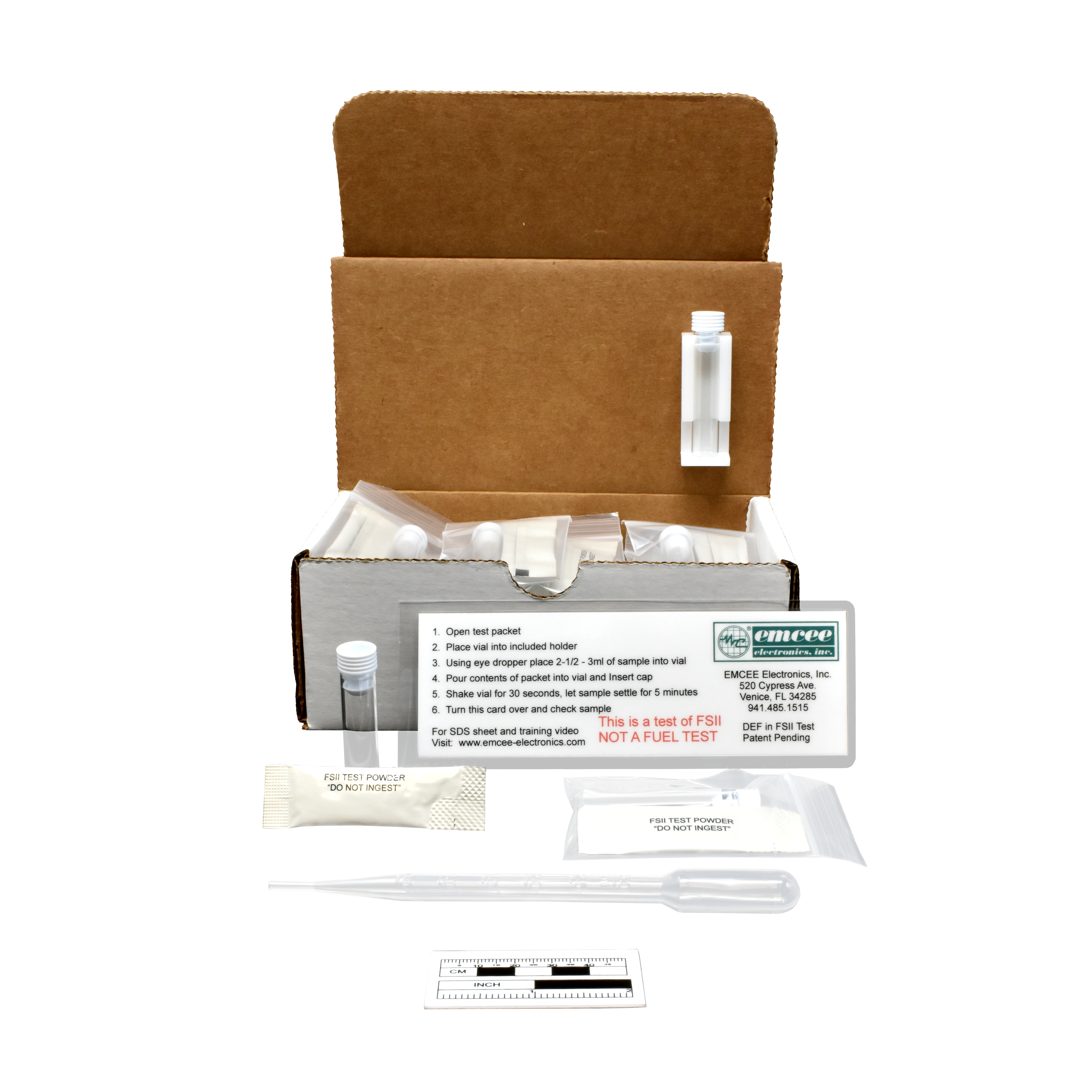
DEFKit® – DEF in FSII Test Kit

Simple Field Test to check for Diesel Exhaust Fluid (DEF) in the refueler
Anti-Icing Additive reservoir! (Fuel System Icing Inhibitor/Prist®/DiEGME)

No training, no instrument needed!

Protect aircraft from DEF contamination when refueling with additive injection. Avoid the potentially catastrophic effect of FSII cross contamination with DEF.

For use by mechanics and pilots. Recommended for use after every filling of the additive reservoir. Comes in a pack of 10.

Developed by Emcee Electronics and marketed by Gammon Technical Products, this kit can detect DEF in anti-icing additive down to as low as 2%.

Simply follow these instructions. (The operator must not be blue/green color blind!)

Procedure

  1. Using the supplied pipette, collect and dispense 2 mL of FSII from the reservoir into the supplied clear vial. (As close as possible to 2 mL using the pipette)
  2. Open and empty the contents of the powder packet into the vial, replace the stopper.
  3. Shake the vial vigorously for at least 30 seconds.
  4. Compare the vial to the color chart included. If blue in color, this is a serious failure, 10% or more of DEF. If you do not see blue, THE TEST IS NOT OVER, proceed to step 5.
  1. Place the vial on a level surface and wait 5 minutes. If the sample remains cloudy white, top and bottom, it is a pass, if the powder settles to the bottom or turns blue, there is 2-10% DEF and this is a fail. (Note, there is no way to detect DEF in jet fuel, only in the additive itself)

IMPORTANT WARNING! If the test is a failure, the reservoir, the entire additive injection system and refueling equipment downstream of the injection point must be considered contaminated. Aircraft fueled with additive, at least since the reservoir was last filled, should be considered not flight worthy, notified and grounded until it can be determined that they are safe to fly. If already in flight, the pilot should be notified and told to land safely as soon as possible. Aircraft previously fueled must also be considered to be at risk until such time that you are SURE AS TO WHEN the DEF got into the reservoir.

The aircraft manufacturer must be consulted on making the aircraft flight worthy. DEF is not easily flushed from fuel systems and no complete and proper method is known at this time for its removal, although hot water has been used to clean up spills. Unsafe levels of residue may still remain.

Made in USA by Emcee Electronics, Venice, Florida

Shelf life: 18 months from date of manufacture

Bulletin 181: DEFKit®2024-12-30T17:44:45+00:00

Bulletin 180: Mini Gammon Gauge

Mini Gammon Gauge Differential Pressure Indicator

The First High-Quality, Inexpensive Direct Reading Differential Pressure Indicator

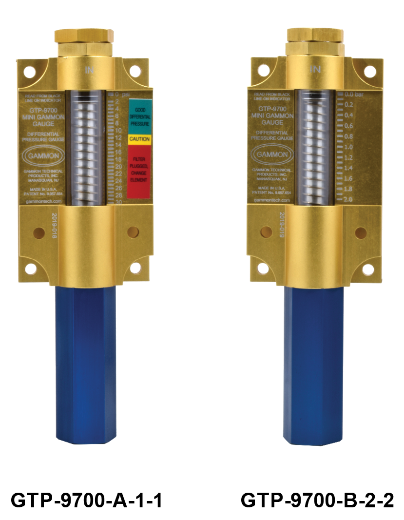
In 1966, Gammon Technical Products introduced the Gammon Gauge, which quickly became the world’s #1 aviation fuel filter differential pressure gauge. In 2017, we are pleased to introduce the new, patented, smaller gauge, made to the same unparalleled quality standards.

Calibration is simple and does not require a gauge laboratory. Use GTP-2305 or any three-way valve. Our test procedure is accepted by the USAF, Army, Navy, and all major oil companies and airlines in the world as all you need to do to check the accuracy of the Gammon type DP indicator.

  • 100% made in the USA

  • Aluminum and stainless steel construction

  • 0-30 psi design range

  • 0-450 psi operating pressure

  • Built in, cleanable filter

  • Ultraviolet protected

  • Viton GLT seals good -40° to +130°F

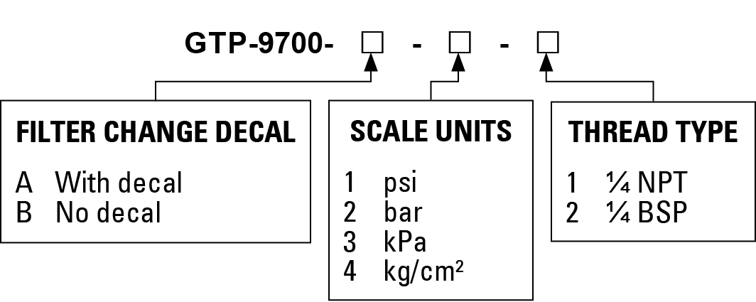
  • Available in psi, bar, kPa, and kg/cm² scales

  • Accurate ±0.75 psi at any pressure

  • Versions available that meet EI-1587 and industrial specifications

How to Order

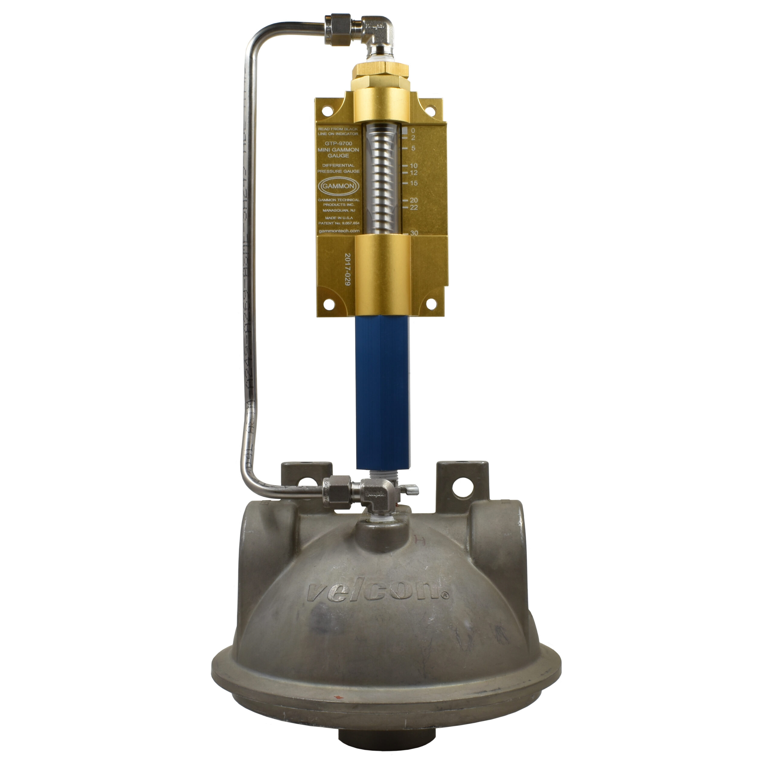
Mini Gammon Gauge Mounting Kit
GTP-9739

This mounting kit allows the Mini Gammon Gauge to be installed on either Velcon VF-61 or Facet VF-22, if pre-drilled and tapped.

Mini Gammon Gauge Control Systems

Protect Against Filter Element Bursting
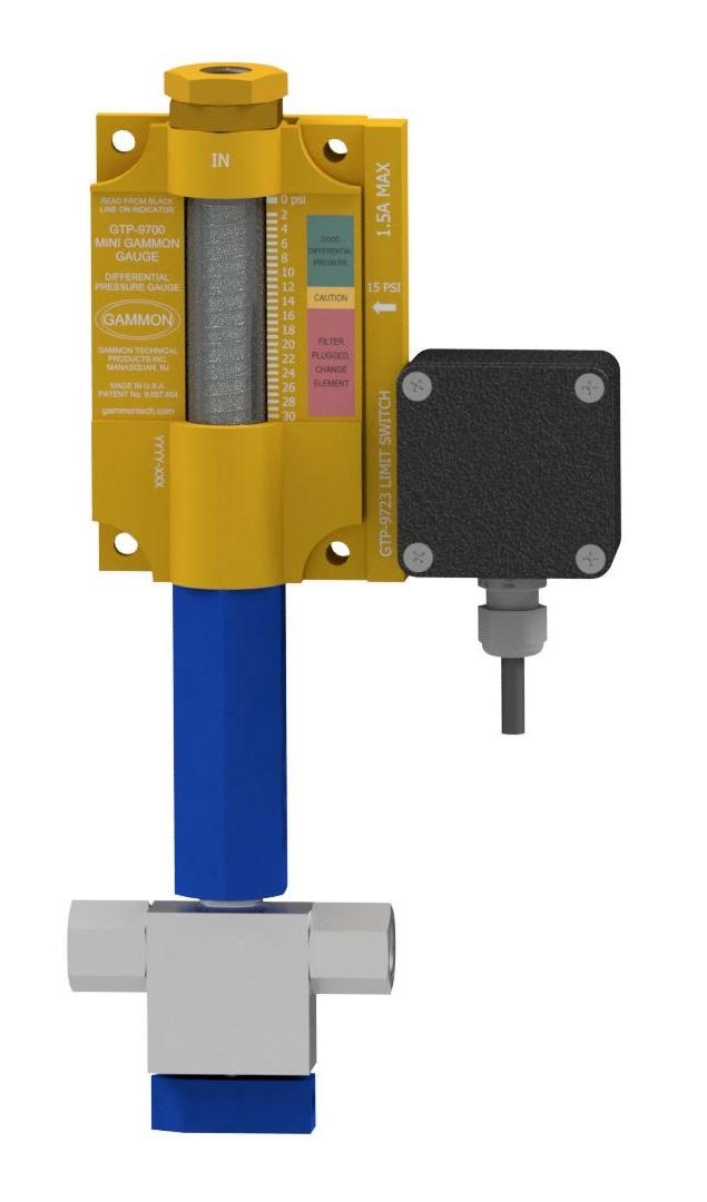
Add a Differential Pressure Switch to the Gammon Gauge
Sound Alarm – Stop Flow – Turn on Second Filter
Normally Open or Normally Closed, Fail Safe

If differential pressure suddenly increases or a facility is operated without personnel monitoring the differential pressure, filter element failure can occur. This new switch is unique. It adds differential pressure control at a low cost using a non-powered proximity switch. This simple double-sealed switch is ideal for use in PLC (miniature computer) and relay controlled systems. The connection box is rated NEMA4X.
Control operations are also available if you don’t plan to use an external control. We have weather-tight and explosion-proof versions.

We strongly recommend a three-way test valve for properly testing the Mini Gammon Gauge and Proximity Switch and/or system.

Any Mini Gammon Gauge can be converted to include the new proximity switch.

Note: To meet IATA JIG Bulletin 58, order the “BKS” option for key switch reset and test functions. The ATA-103 does not require this. For vehicle mounting, we recommend the weather-tight housing.

How to Order

Example:

GTP-9980B-P-RH-12-B-0 is a differential pressure gauge with a normally closed switch as follows: mini gauge with test valve, 30psi scale, switch on right side, 12 VDC, enclosure is weather tight which includes light and push to test feature, no solenoid valve, and low temperature o-rings.

GTP-9980B-P-RH-12-BKS-0 is the same as above except the enclosure has two key lock switches for test and reset as per IATA JIG Bulletin 58.

Notes:

  1. GTP-9980 has a normally open switch. The switch closes upon high differential pressure. If the cable to the controller is cut, high differential would never be detected.
  2. GTP-9980B has a normally closed switch. The switch opens upon high differential pressure. If the cable to the controller is cut, the system would go into alarm notifying the operator that something is wrong with the system.
  3. If a system is purchased without the controller (no enclosure), both types of switches are still available. When a complete system is ordered with an enclosure, it is our policy to provide a GTP-9980B fail safe system unless otherwise requested. The difference is in the internal wiring and components in the controller.

Bulletin 180: Mini Gammon Gauge2024-12-30T17:44:19+00:00

Bulletin 179: Refueler Vehicle Flow Accessories

Defueling Eductor
TL-8856

When defueling aircraft, the safest method is to use an eductor. This device generates flow and a mild vacuum. This allows the truck to defuel aircraft at a controlled rate and a controlled vacuum, to protect the aircraft. Excess vacuum can cause damage to the aircraft fuel tanks, which are often part of the wing. The primary adjustment is made by controlling the pump
speed/flow rate on the refueler.

The TL-8856 eductor is designed to match or exceed the performance of other eductors on the market and do so with one less gasket and a lower price. Our eductor is rated up to 280 gpm. In addition, it is cast of 356-T6 aluminum, 100% made in the USA.

3” x 3” x 2” IPS (Victaulic)

Recovery Tank Eductor
GTP-486-5

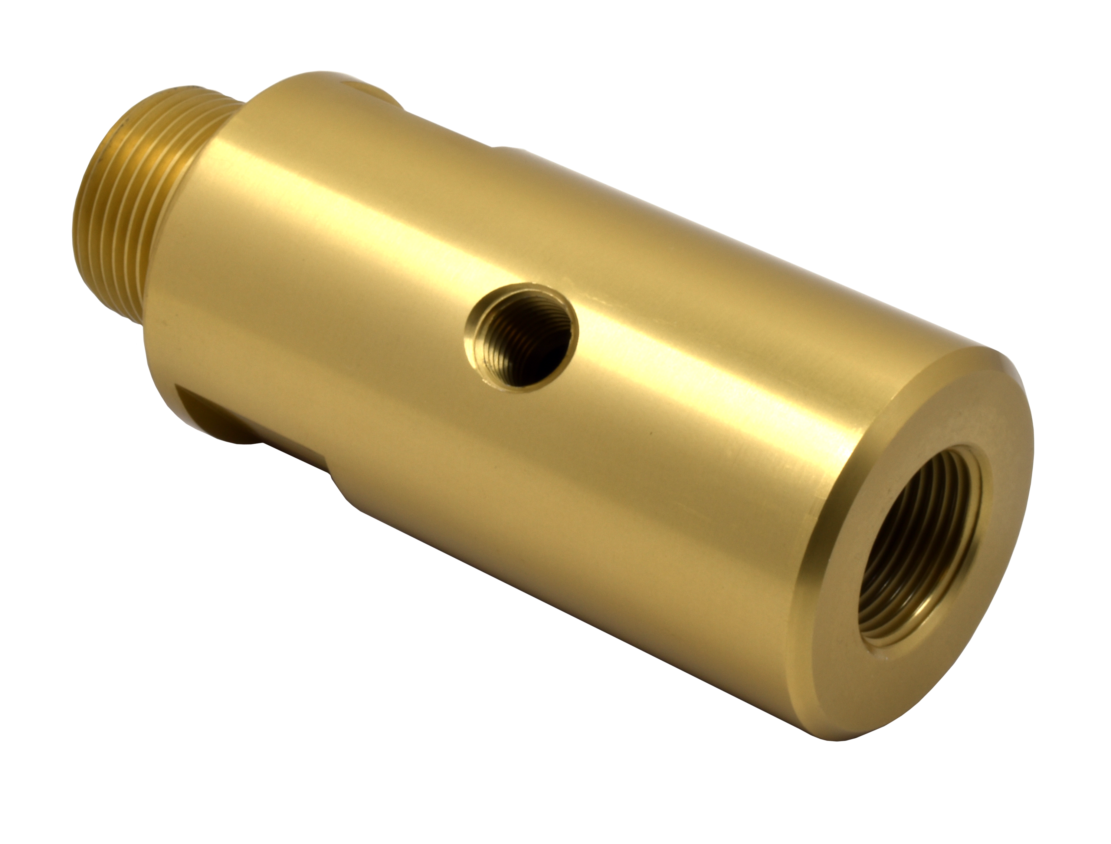
Recently redesigned for even greater performance, this eductor is designed for recovering clean fuel from an expansion/recovery tank on a refueling vehicle. For optimal performance, the suction line should be 1/2” pipe or tubing at a minimum and the suction line ball valve should be 3/8” full port or 1/2” standard port. 100% made in the USA, aircraft grade aluminum.

3/4 NPT x 1 NPT x 3/8 NPT

Venturis

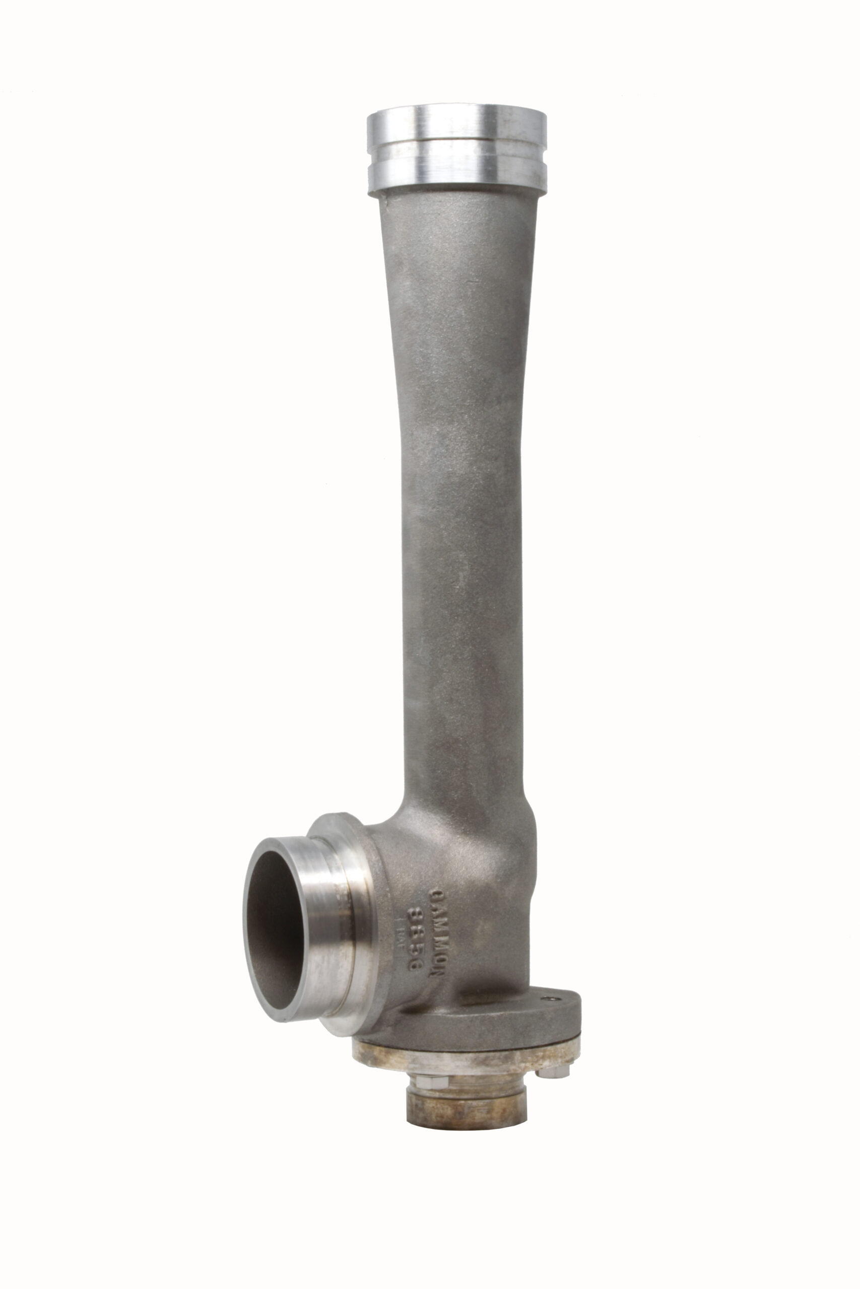
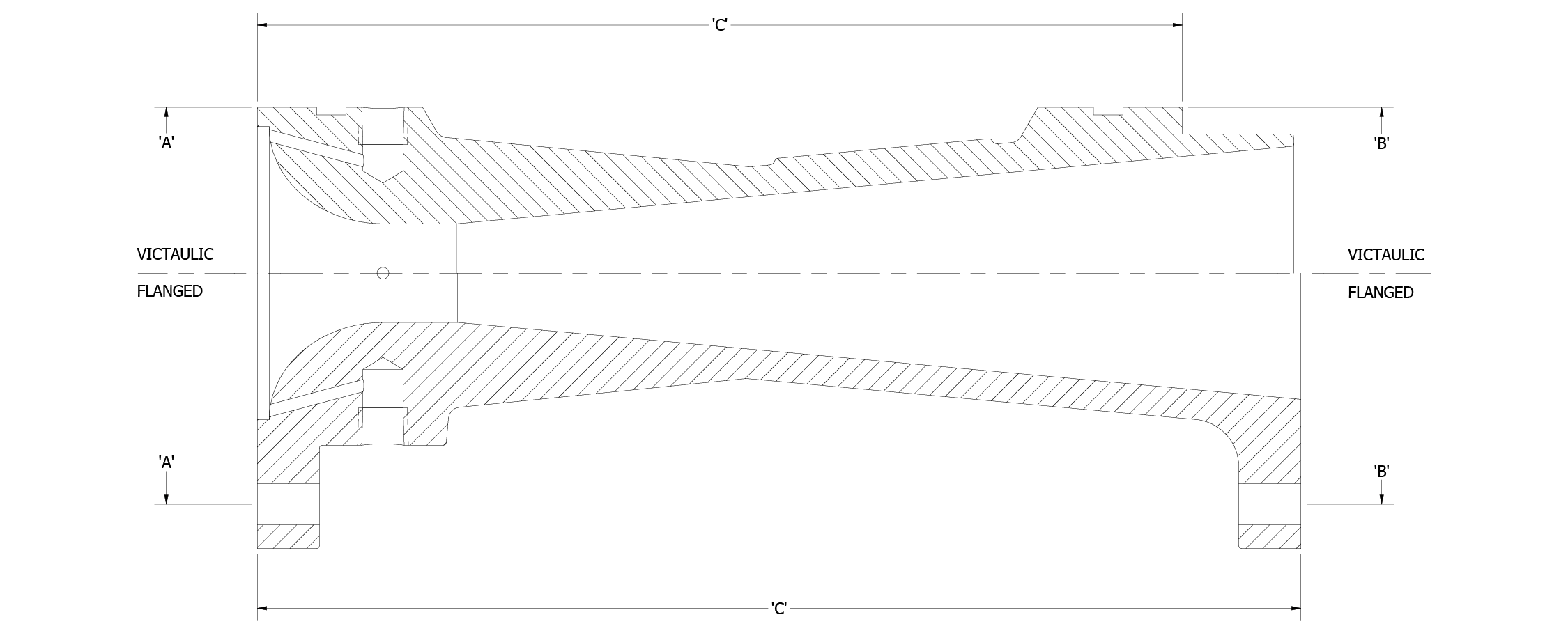
To refuel aircraft at the highest possible flow rate, a refueling vehicle must control the pressure accurately at the nozzle to approximately 45 psi. Because of pressure drop in the hose reel and hose, a system flowing at 300 gpm with 45 psi at the nozzle has to have a much higher pressure at the host reel inlet. But pressure drop changes with flow rate. For this reason, Venturis are used to automatically “compensate” for this pressure drop.

As velocity increases, the small opening at the center of the venturi has higher and higher velocity. As the inventor, Giovanni Venturi, discovered over 200 years ago, the pressure decreases as velocity increases. Using careful mathematics, a Venturi can create a “false signal” that can be tuned to match the actual nozzle pressure (or it may be higher in some cases, on the “safe side” with actual nozzle pressure lower). See our GamGram #32.

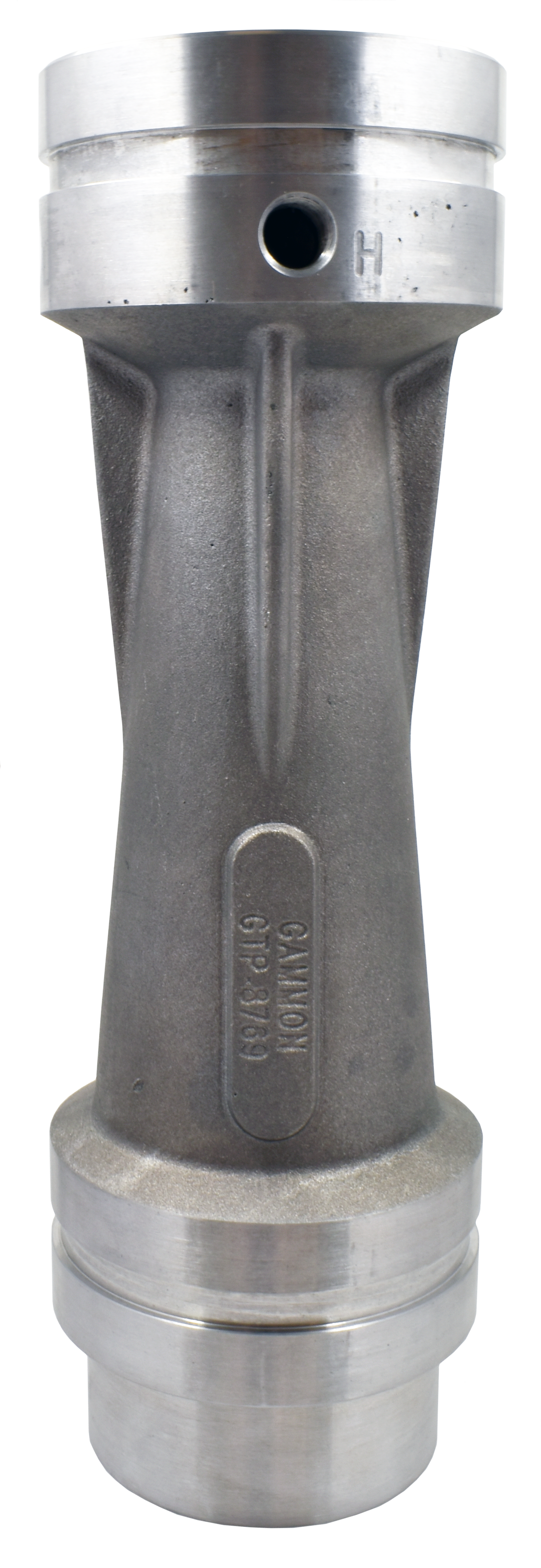
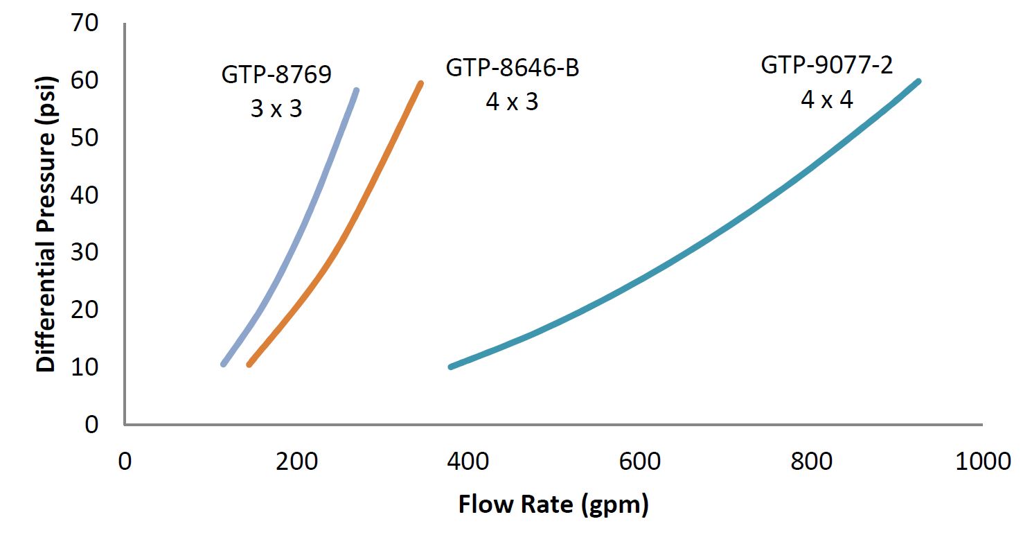
The primary venturi we sell is the 3” x 3” GTP-8769 venturi, made with either flanged (TTMA) or Victaulic connections. It is the highest performance 3” venturi we know of, specifically tuned for 300 gpm. We also make the GTP-8646-B 4” x 3” Venturi with Victaulic connections only.

All Gammon Technical Products venturis are cast and machined in the USA and are 356 T6 aluminum, impregnated against leakage. Rated for up to 150 psi system pressure. Needle valve not included.

Part No. End Style Inlet ‘A’ Outlet ‘B’ Length ‘C’
GTP-8769 Victaulic 3″ 3″ 9.75″
GTP-8769-3 TTMA Flanged 3″ 3″ 11″
GTP-8846-B Victaulic 4″ 3″ 14.1″
GTP-9077-2 Victaulic 4″ 4″ 14.1″

Bulletin 179: Refueler Vehicle Flow Accessories2024-12-30T17:44:01+00:00

Bulletin 175: Auto-Air® High Performance Air Eliminator

Introducing a breakthrough air eliminator design. The Auto-Air® Air Eliminator utilizes a unique “rocker” seal which allows 4 times the air relief of similar sized air eliminators.

  • Jet fuel, aviation gasoline, diesel, or gasoline rated (0.7 to 1.1 SG density)
  • Full 1/8” (6.4mm) relief orifice
  • 160 psi air relief (fully open)
  • 300 psi system pressure
  • 1200 psi stricture pressure
  • 3/4” NPT, BSPP, or ANSI flanged
  • Made in U.S.A.
  • Fully rebuildable, Viton sealed
  • 100% stainless steel construction

Filter vessels need to exhaust (eliminate) any incidental air that may get into the fuel system. Our Auto-Air® air eliminator is a small, compact, high-performance unit which is also strong and rebuildable.

In the past, simple air eliminators have either under-performed, tended to leak, or were just too weak for hard service. The Auto-Air® is the answer. It relieves 24 scfm at 150 psi.

GTP-9363-A

Bulletin 175: Auto-Air® High Performance Air Eliminator2025-01-13T14:32:15+00:00

Bulletin 173: SkyHawk Overwing Nozzle

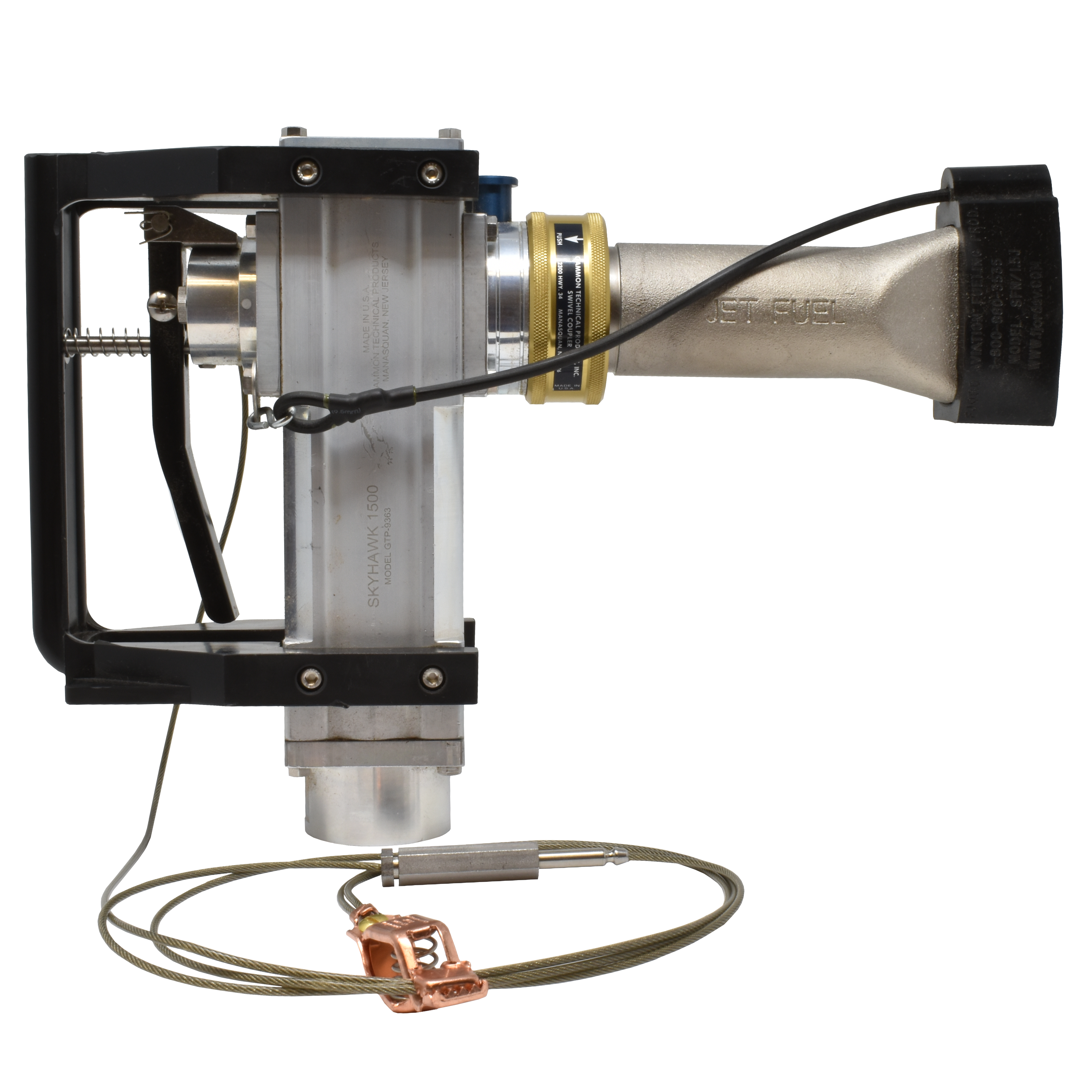
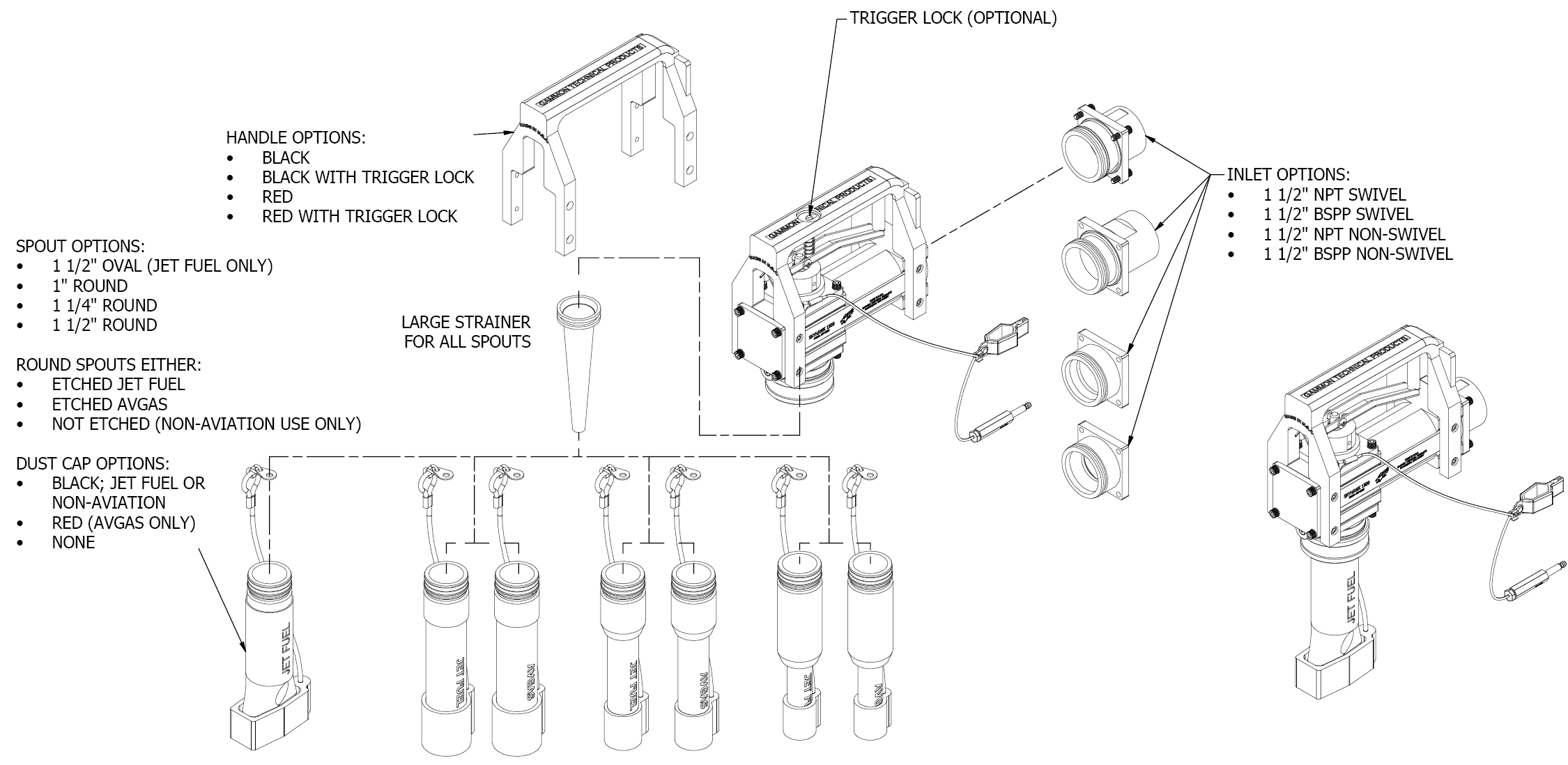
  • Heavy duty 1 1/2″ NPT swivel inlet

  • Quick change swiveling spout design – QD type

  • Inexpensive to repair – all seals independently replaceable

  • Easy operation, fingertip sensitivity, and adjustable closing speed

  • Swivel interlock compatible design

  • Survived 16 months in a continuous duty test at a major international airport

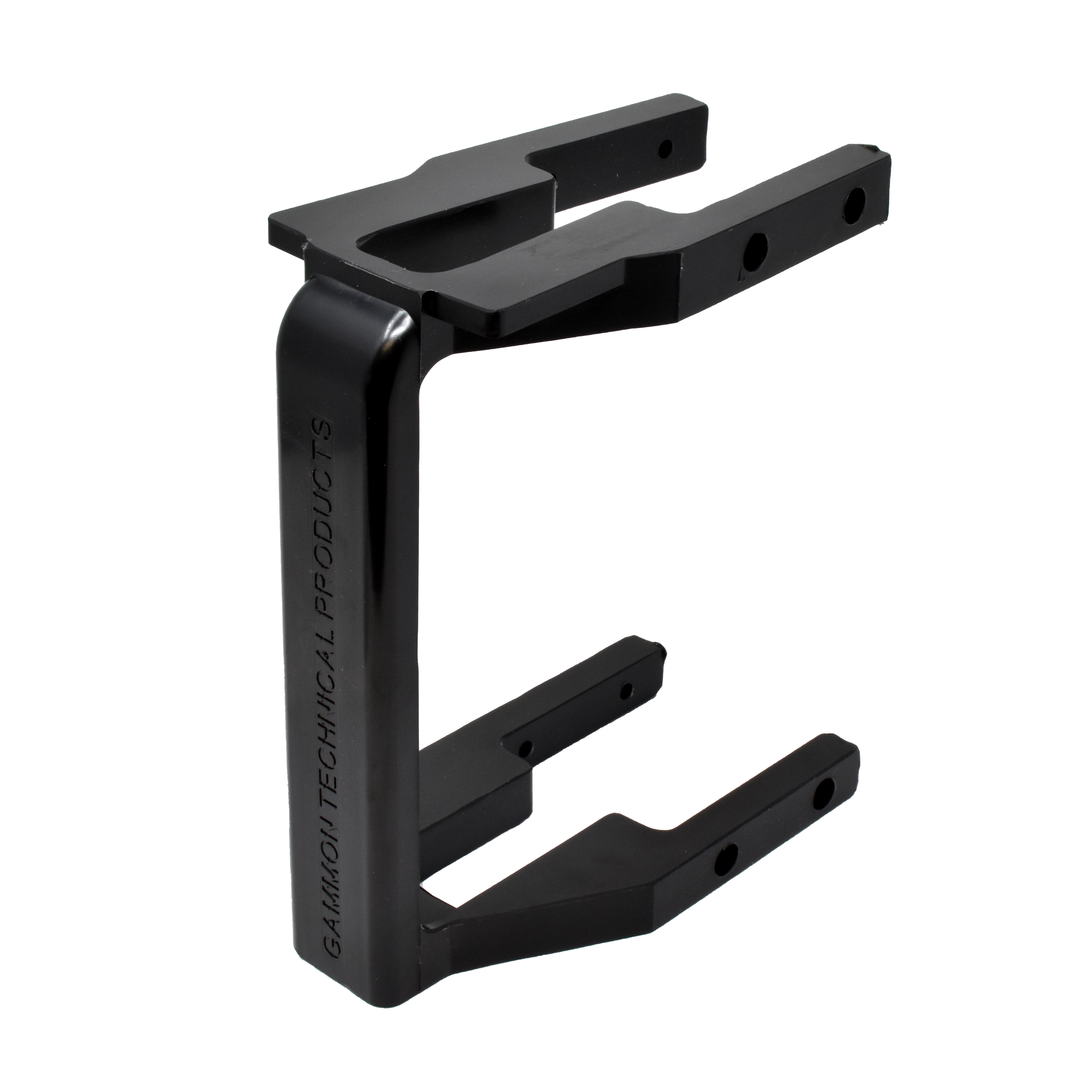
  • Rugged polyurethane handle guard with side protection

  • Seals well to -50°F and compatible with all aviation fuels, bio diesel, and jet

  • Spout dust covers and retainer are polyurethane

  • No plastic components (except PTFE poppet bushing), no cast metal parts, 300 series stainless steel shaft and fasteners

  • Spout storage holder available (for second spout)

  • GTP-9644 check valve available when ordering or as a retrofit.

GTP-9363-25A
spout storage holder

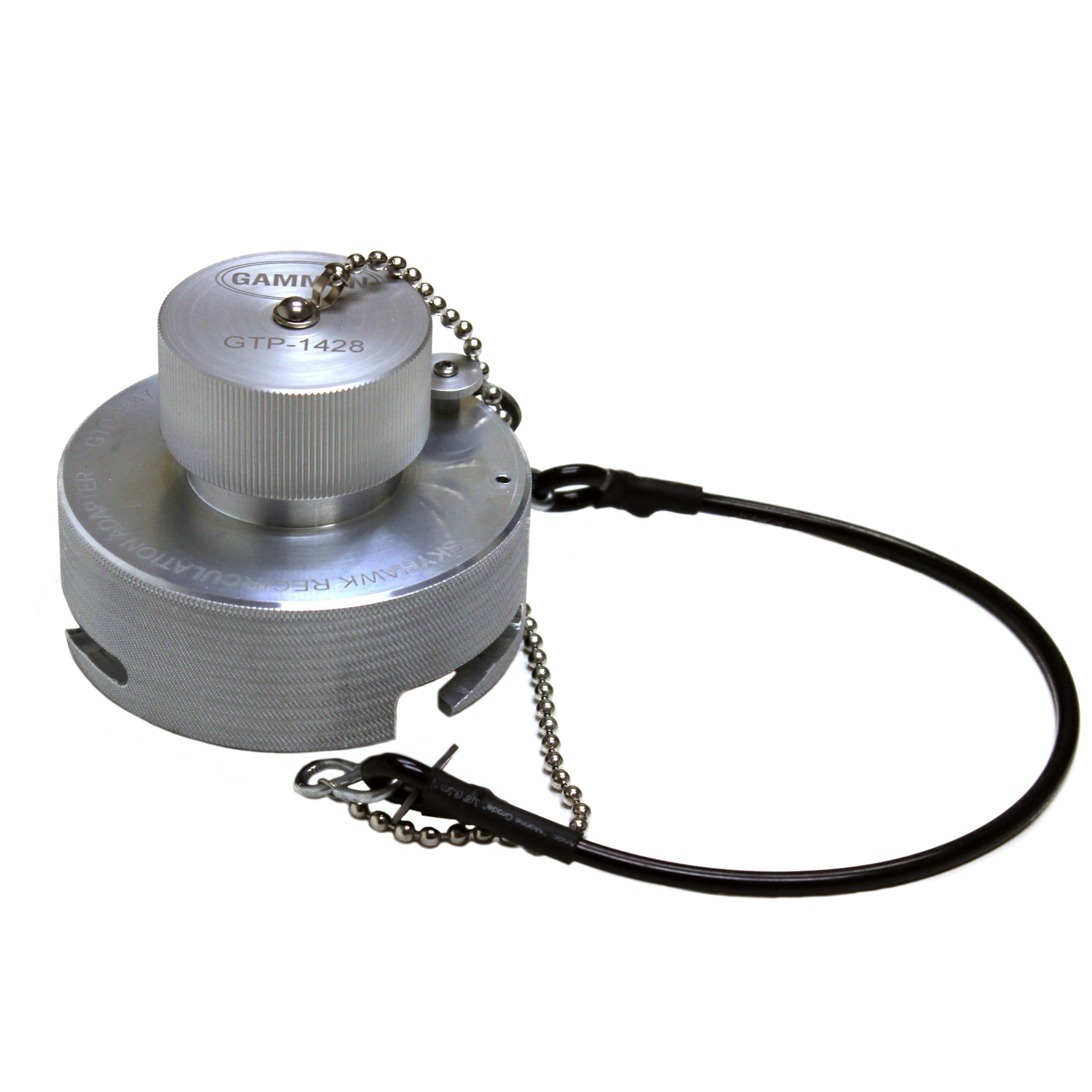
Safely Recirculate Overwing Hoses with the SkyHawk Recirculation Adapter

JM-9647
SkyHawk recirculation adapter

In the past, recirculation of your overwing nozzles required climbing on top of the truck. Aside from the potential for the operator falling, you can also damage the nozzle by dropping it, and in addition, splashing fuel into the tank is a static fire hazard.

The SkyHawk Recirculation Adapter (patent pending) solves this problem. Simply disconnect the standard spout and connect the JM-9647 adapter to the SkyHawk nozzle. Then connect it directly to the bottom load adapter on the truck.

Squeeze the trigger and recirculate at up to 100 gpm. The only downside is that upon disconnection, you need to catch about 3 oz of fuel from the adapter. Dual interlocks help prevent accidental disconnection.

Replacing your bottom load dust cap? We include an inlet dust cap and lanyards so you can replace the existing (or missing) bottom load dust cap with the SkyHawk Recirculation Adapter, making it a high quality solid aluminum dust cap as well as a recirculation adapter!

Uses a genuine Meggitt (Whittaker) F117 nose seal for excellent sealing integrity. (P/N 2713509)

Constructed of 100% aviation grade aluminum with S/S trim and, of course, manufactured by GTP in the USA.

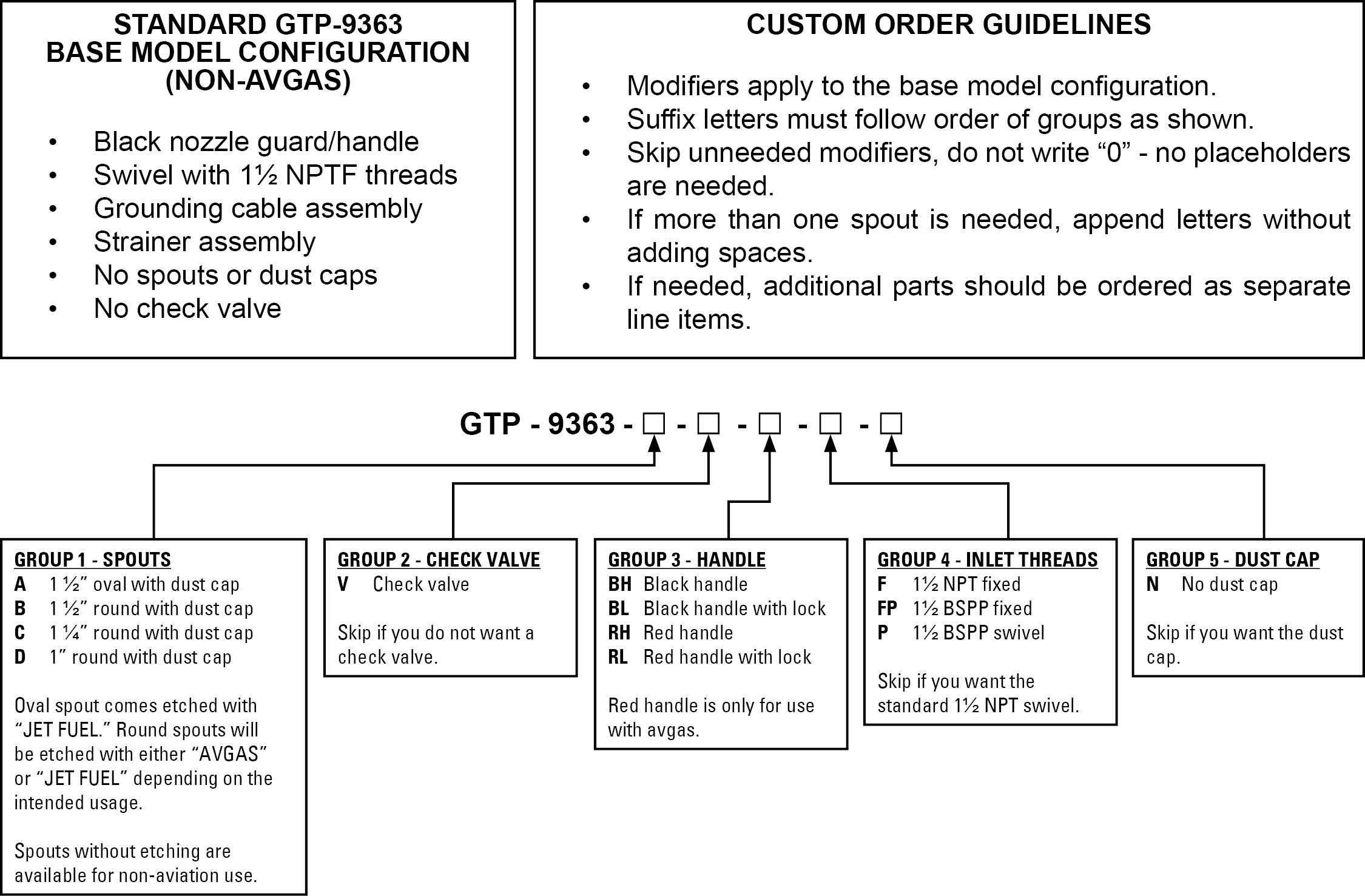
How to Order the SkyHawk Overwing Nozzle

Examples
GTP-9363-AB-P: Nozzle with both of the 1½ inch spouts with BSP swivel on inlet.
GTP-9363-V-RH: Nozzle with no spouts, a check valve, and a red handle.

Parts & Accessories

GTP-9644
check valve assembly

GTP-9363-9
SkyHawk handle, black

GTP-9363-9R
SkyHawk handle, red

GTP-9363-J150-A
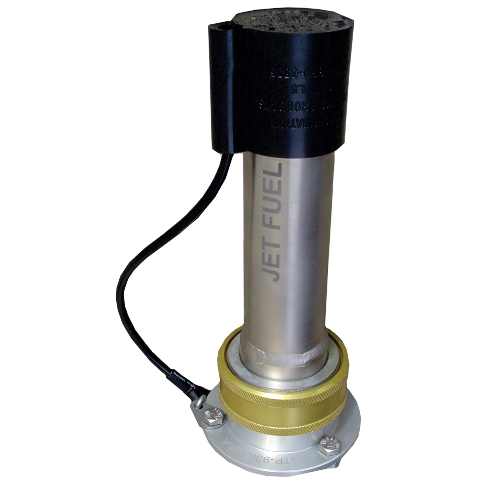
1 1/2″ oval jet fuel spout with lanyard assembly

GTP-9814-51
SkyHawk to OPW spout swivel adapter kit, 1 1/2″ round

Bulletin 173: SkyHawk Overwing Nozzle2024-12-30T17:43:25+00:00

Bulletin 171: Gammon DP Guard

Simple and Inexpensive

Stops Flow if Differential Pressure on a Filter Vessel Exceeds a Safe Level

For both powered and unpowered carts and trucks

The hydraulic cylinder moves based on the differential pressure sensed across the filter. When differential pressure exceeds the set point, the cylinder closes a toggle valve, stopping flow to a hydraulic or pneumatic deadman or stopping flow to a pilot valve.

Connects to the existing differential pressure gauge lines and existing hydraulic deadman circuit.

No power needed, 2 way hydraulic and 3-way compressed air versions available.

Adjustable set point. It can be simply tested using a 3-way valve (GTP-2305V) or better yet, connect directly to Gammon Gauge with a Push Button Tester. (Special lower flange on Gammon Gauge needed).

Lockable cover, simple, heavy duty design.

Aluminum and Stainless Steel construction.

How to Order

GTP-9425-H
hydraulic DP Guard

GTP-9425-U
air operated DP Guard

Bulletin 171: Gammon DP Guard2024-12-30T17:43:02+00:00

Bulletin 169: Closed Loop MiniMonitor®

The problem in running the MiniMonitor® (a.k.a. “Millipore” TM Millipore Corp.) membrane test for particulate/dirt detection in Jet Fuel is the bucket. Many years ago, the ASTM reduced the problem by changing the sample volume from 3 gallons to just 1, but the hassle of having to deal with buckets of fuel remained – UNTIL NOW.

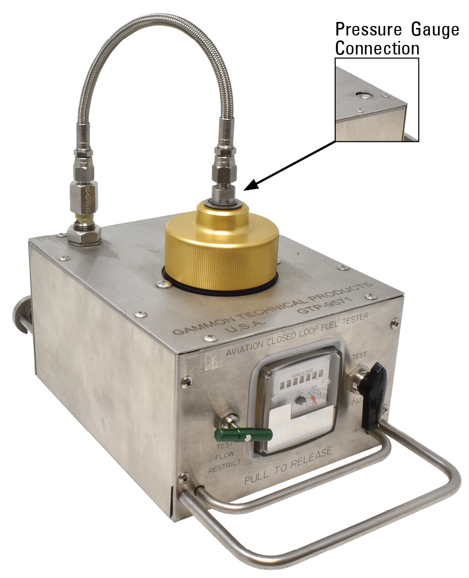
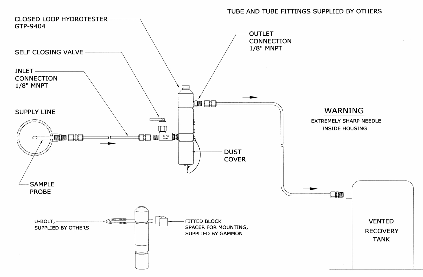
The Closed Loop MiniMonitor® eliminates the bucket. It reduces spills, waste and personnel exposure by keeping the fuel completely inside the fuel system itself. All the test fuel is recoverable. On a hydrant cart, it can be directed to a recovery tank and on a truck or in a fuel tank system, it can be directed back to storage.

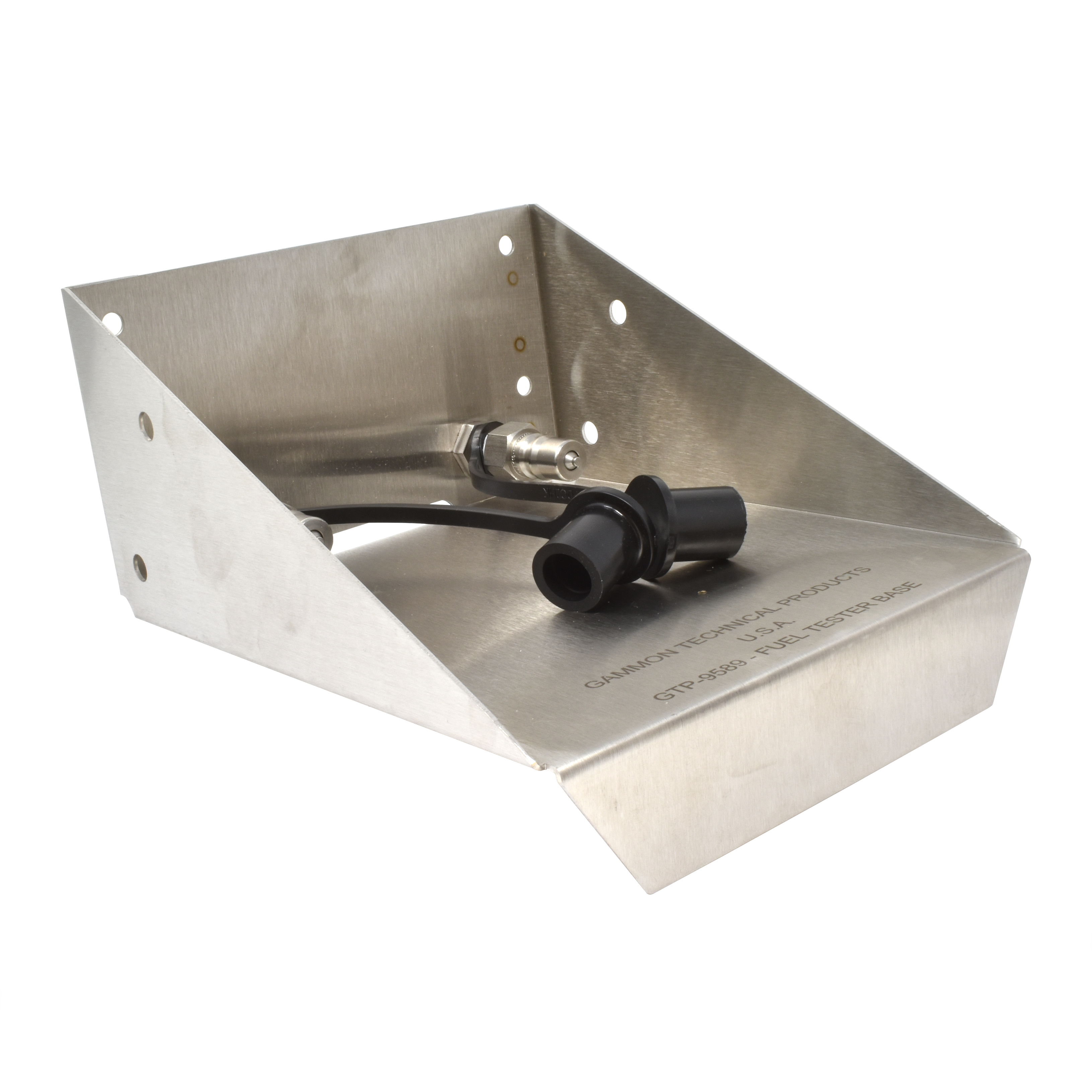
Trays and testers sold separately, mount one tray on each truck and at the fuel farm, buy just one (or two if needed) Closed Loop MiniMonitor®.

Simply put the Plastic Monitor into the Closed Loop MiniMonitor® and then:

  • 1

    Turn the inlet selector valve (optional) to “Filter Inlet” or Filter Outlet”

  • 2

    Turn the control valve to “Flush” and watch the CLMM fuel meter to flush the connection.

  • 3

    Turn the control valve to “Test” and allow 1 gallon to pass through the Membrane in the Plastic Monitor.

  • 4

    Turn the valve to “Off”. (MUST be in the off position before removing cap).

  • 5

    Remove the plastic monitor and evaluate the results.

In addition to the obvious savings over disposing of test fuel and preventing spills, this approach allows you to run tests so quickly and easily that the results have much more meaning that tests run minutes or even hours apart, in which you have to handle buckets of fuel.

QUALITY – Made in America, all 300 series S/S except the meter body (Brass body, Aluminum internal working parts) and monitor holder (Aluminum). The highest quality components available are used.

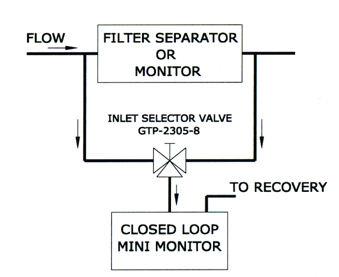
Installation Diagram

How to Order

GTP-9571
Closed Loop MiniMonitor – gallons

GTP-9571-LIT
Closed Loop MiniMonitor – liters

Parts & Accessories

GTP-9609
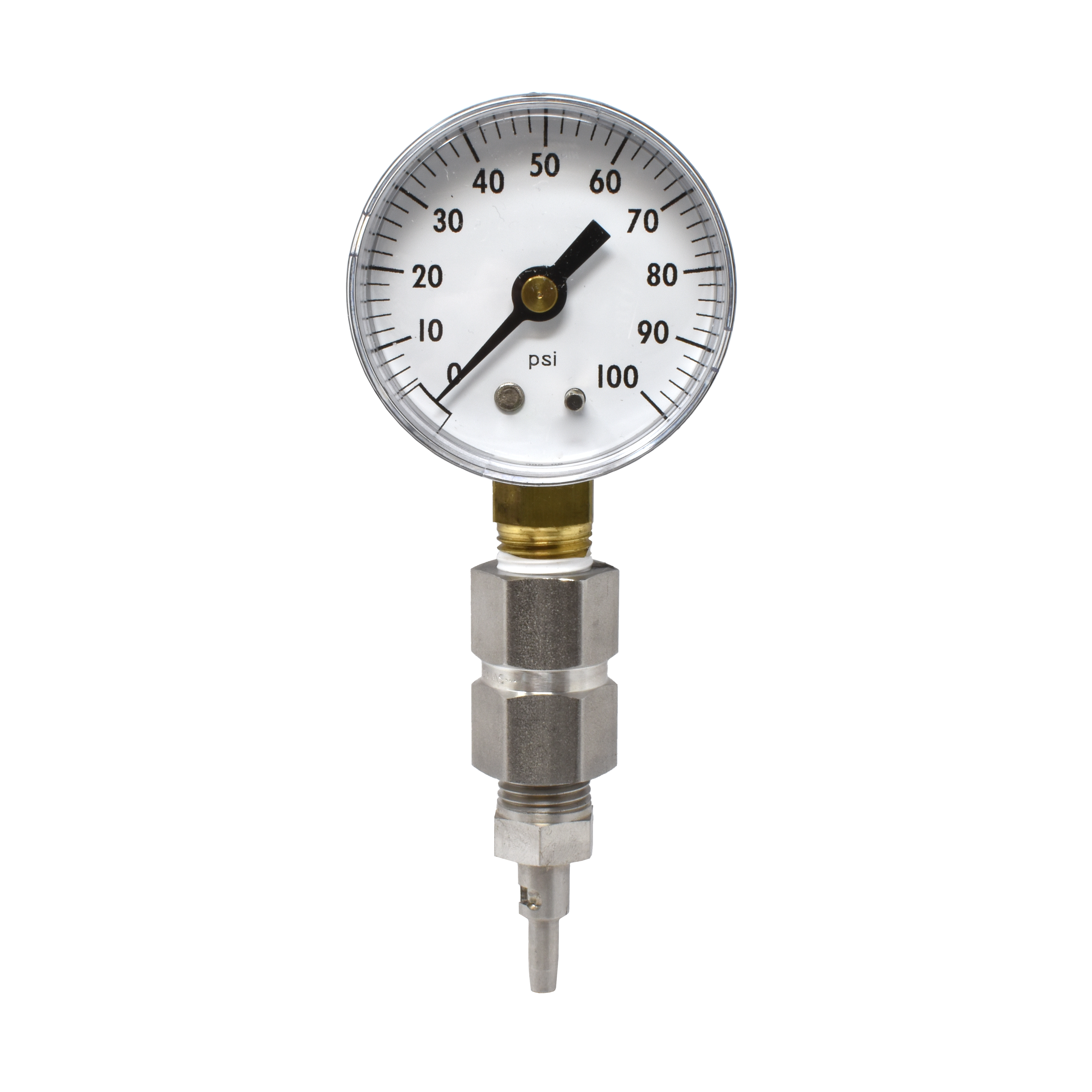
pressure gauge assembly, 0-100psi

GTP-9589
tray assembly

Bulletin 169: Closed Loop MiniMonitor®2024-12-30T17:42:44+00:00

Bulletin 168: Closed Loop HydroKit® Tester

HydroKit® Testing without Collecting a Sample

Although a very good and simple water detector, the Velcon HydroKit® has one weakness; the fuel sample must be taken in a jar. This results in a potential mess; the operator must first have a clean, dry container, and then dispose of the excess sample and store the jar in a safe place.

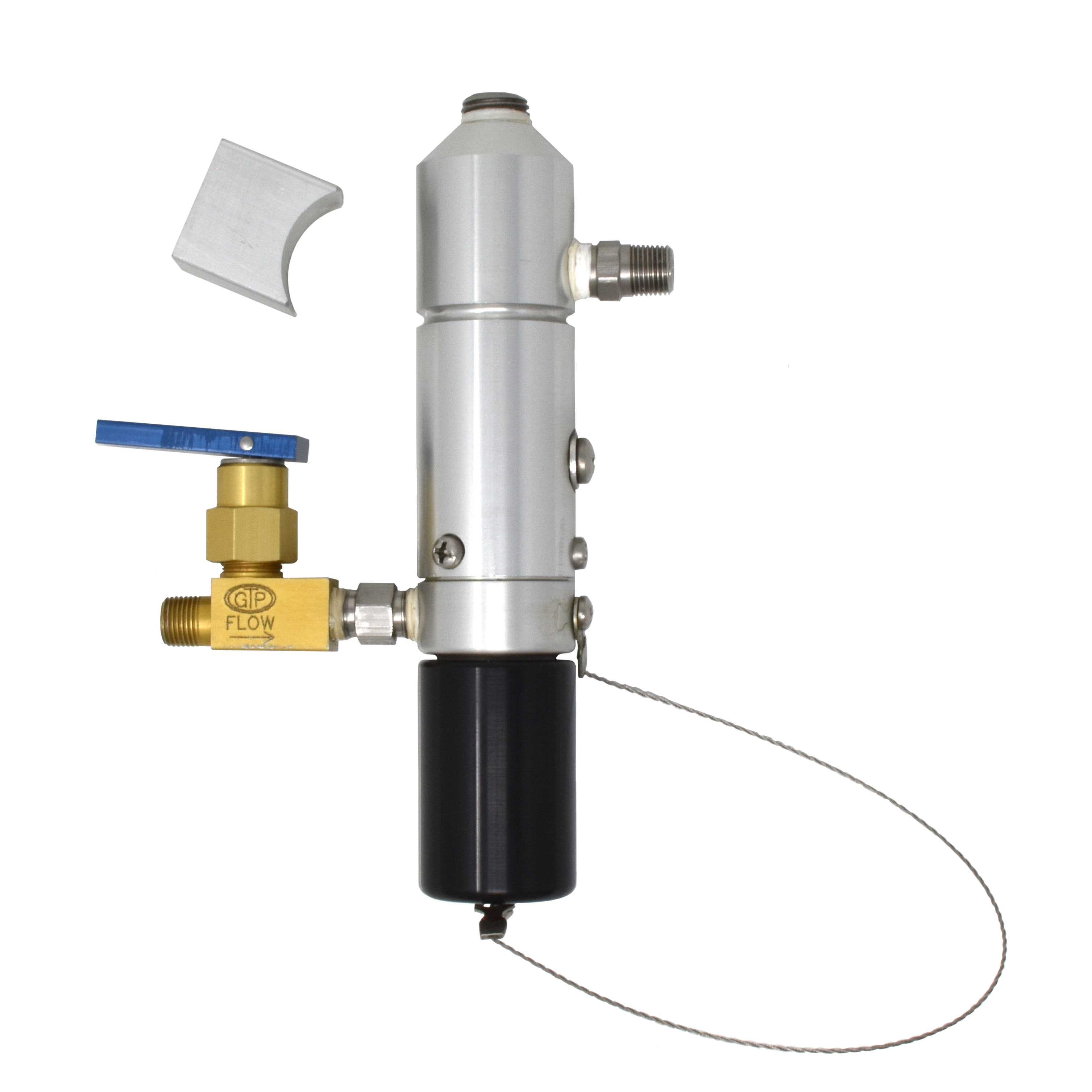
Not any more! The Gammon Closed Loop HydroKit® Tester eliminates sample containers! All you need to handle is the HydroKit® test tube itself and the fuel sample is never exposed, even to the atmosphere. Patent pending.

Saves time, eliminates waste fuel and eliminates the chance for spillage.

Operation

  • 1

    During system fuel flow, operate the self-closing valve for a few seconds to flush the inlet line and fill the Tester with a representative sample of fuel from your system. The flush fuel goes automatically to the recovery tank or back to storage.

  • 2

    Remove dust cover, place the HydroKit® tube into the bottom of the tester and push up. This automatically opens an internal vent valve and the vacuum in the tube draws in the fuel sample.

  • 3

    HydroKit® fills correctly in a couple of seconds. Remove and then replace dust cover.

  • 4

    Evaluate color change of powder in the tube.

Bulletin 168: Closed Loop HydroKit® Tester2024-12-30T17:42:21+00:00

Bulletin 163: Static Bonding Cable Reel

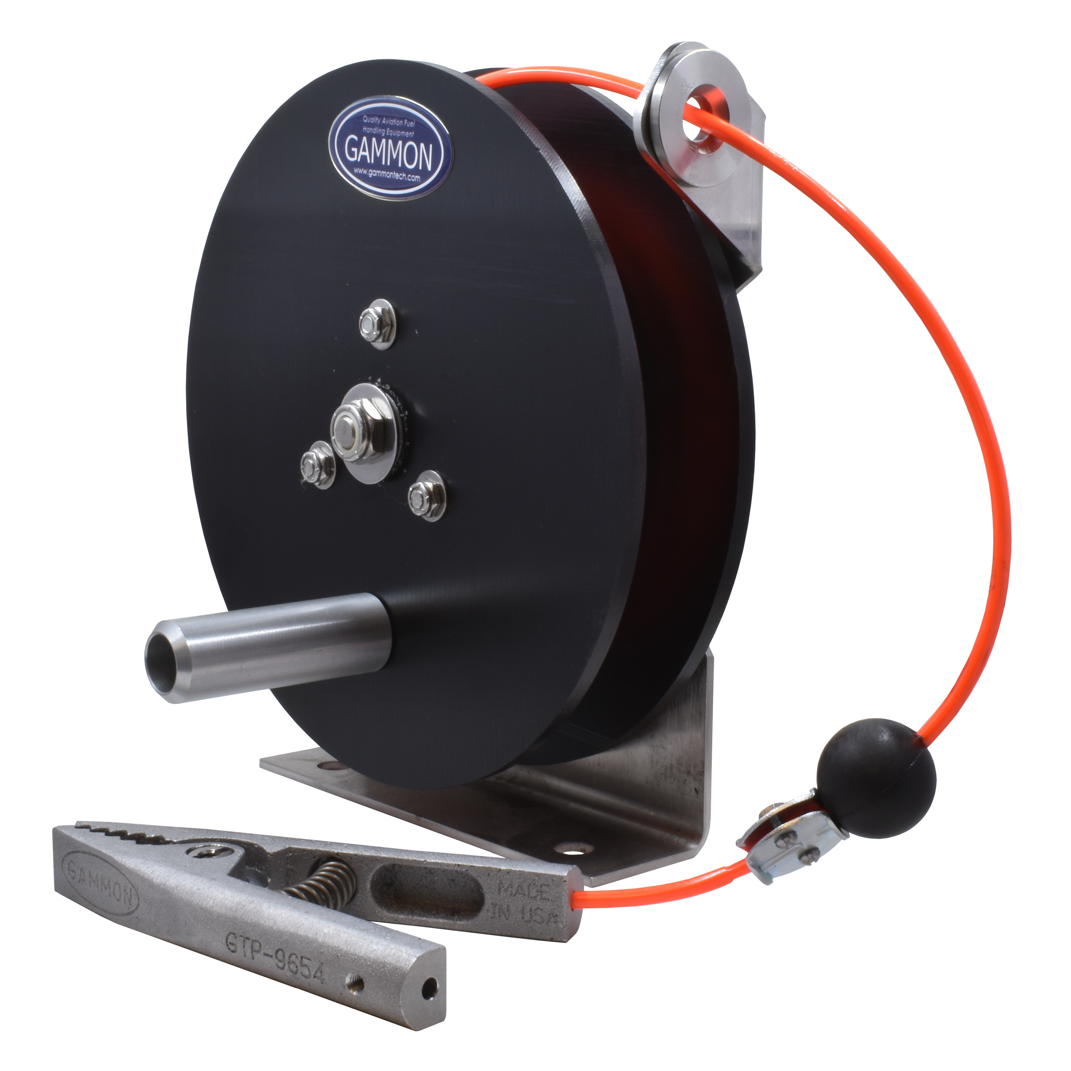
The simplest form of static cable reel is the manual rewind design. This simple reel incorporates all the features you want – and need. Can be mounted on a horizontal or vertical surface.

  • Static conductive nylon discs

  • Aluminum hub with conductive corrosion protection

  • Stainless axle, and bracket guide

  • 1/8” OD cable – over 200’

  • 3/16” OD cable – over 100’

  • Height: 9 ⅝”

  • Width: 6 ⅜”

  • Depth: 9”

  • Mounting plate: 7” x 2”

  • Weight (without cable): 5 lbs.

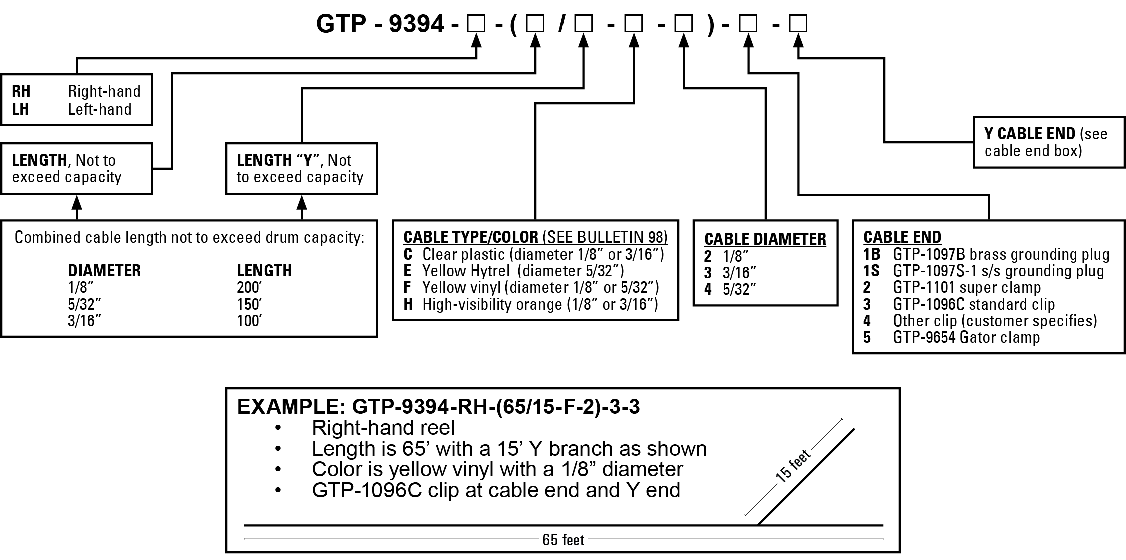
How to Order

Bulletin 163: Static Bonding Cable Reel2024-12-30T17:42:04+00:00
Go to Top