Bulletin 113: Anti-Ice Additive Pump

Bulletin 113: Anti-Ice Additive Pump

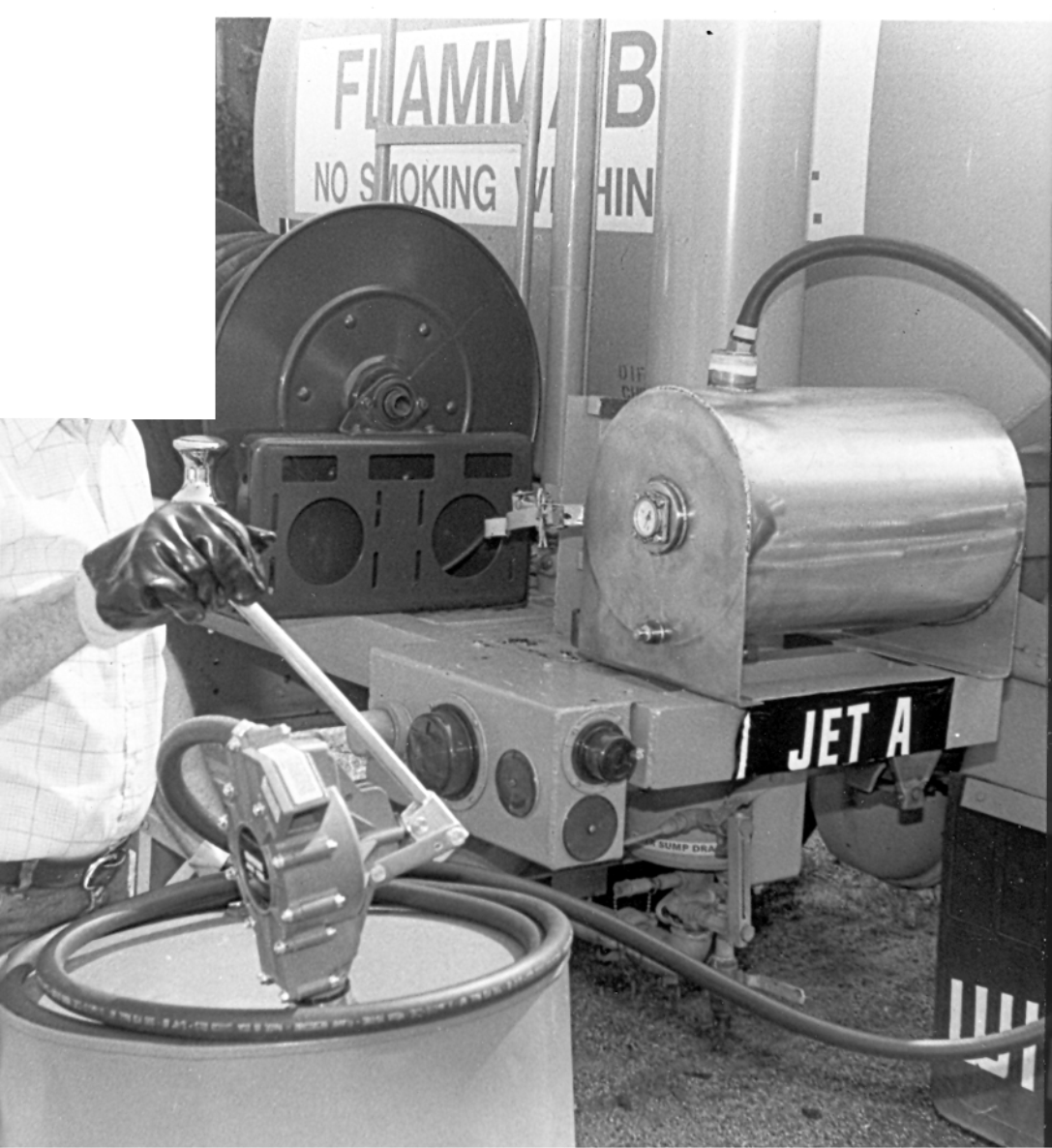
Hand Pump for Anti-Icing Additive

also known as PRIST or DiEGME
  • Save money by purchasing additive in 55-gallon drums instead of 5-gallon cans

  • Fill your reservoir with minimal exposure of personnel

  • No heavy 5-gallon cans to lift

  • Special non-drip hose-end check valve

  • Seals and hose are compatible with anti-icing additive

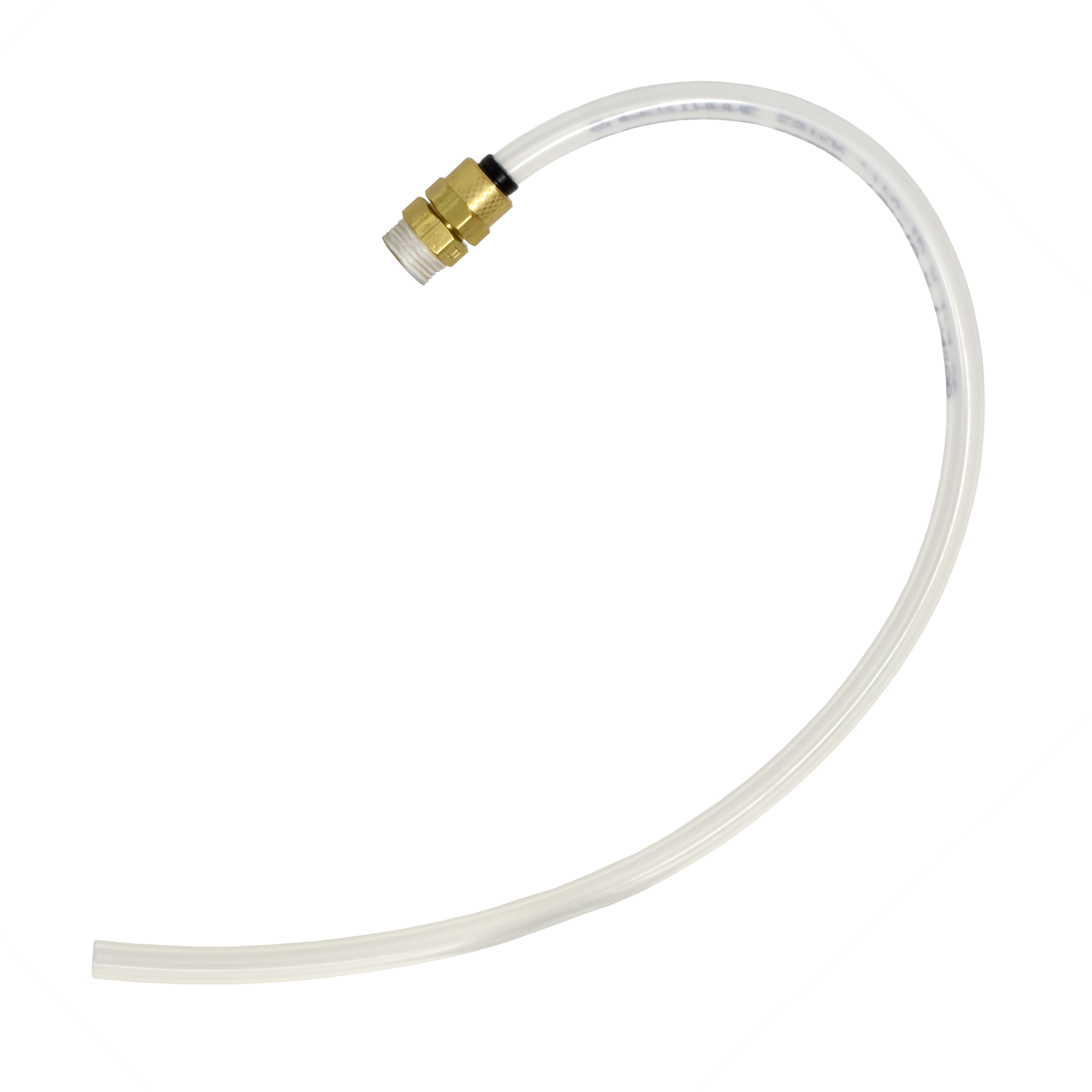
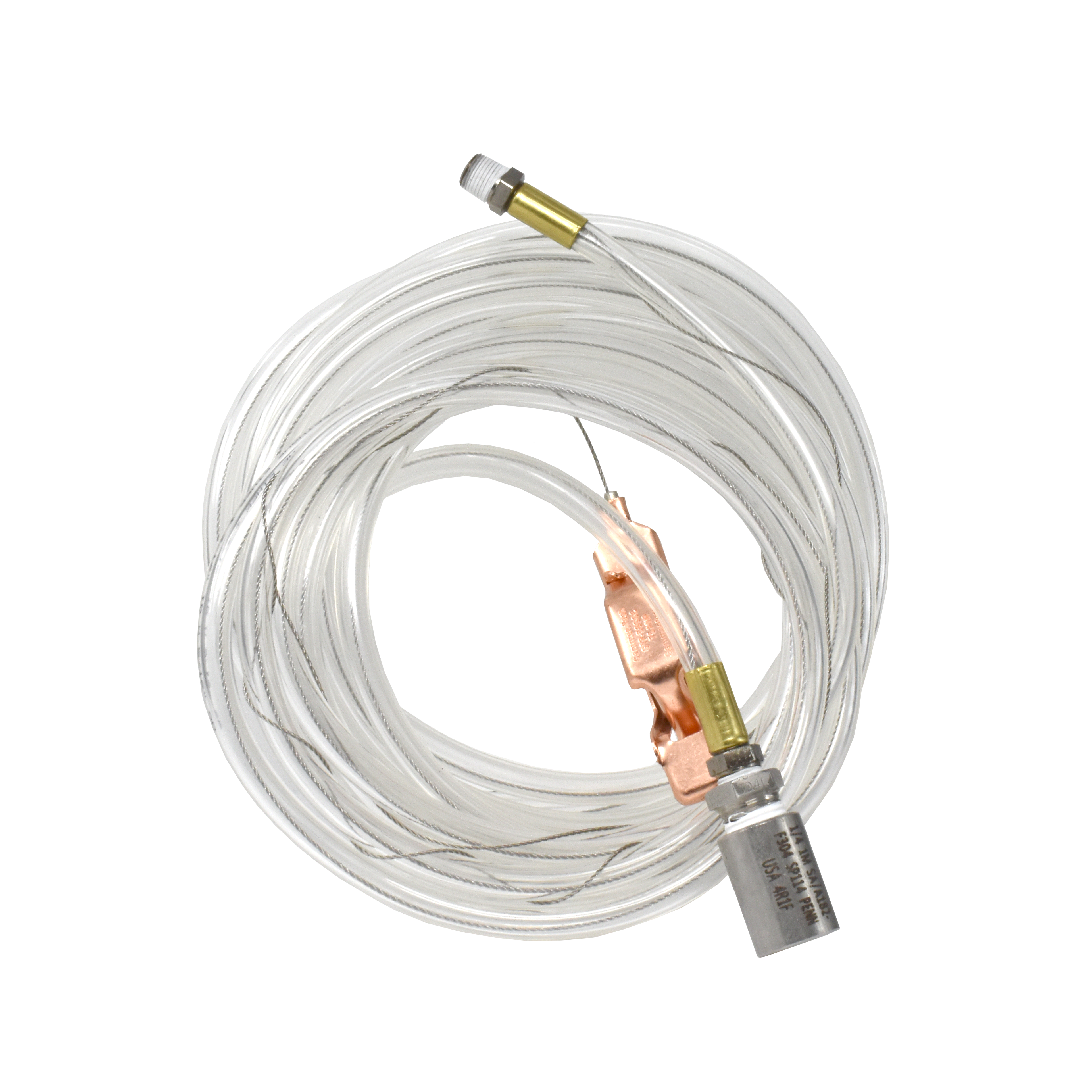
Handling anti-icing additives such as PRIST® can be dangerous because of the hazardous nature of the chemical. We offer a polyester hand pump equipped with neoprene seals for use with DiEGME additive. The pump has a 2-inch bung with 3/4 inch outlet. TL-1938H includes a 12 foot long, 3/4” PTFE lined hose assembly with check valve for safe handling. The hose is also available separately.

We also are your source for additive injection systems for any application. Flow rates from 10 to 1,000 GPM. For further information, refer to Bulletin 36.

Ordering Information

TL-1938
hand pump (NOT for use with anti-icing additive)

TL-1938-1
hand pump with neoprene seals for use with anti-icing additive

TL-1938H
hand pump with neoprene seals and hose assembly

TL-1938-SK
neoprene seal kit to fit -1 and -H

TL-3489-1
12 ft long, 1/4″ PTFE lined hose assembly with check valve

Bulletin 113: Anti-Ice Additive Pump2024-10-16T17:29:34+00:00

Bulletin 100: API Gravity and Density Calculators

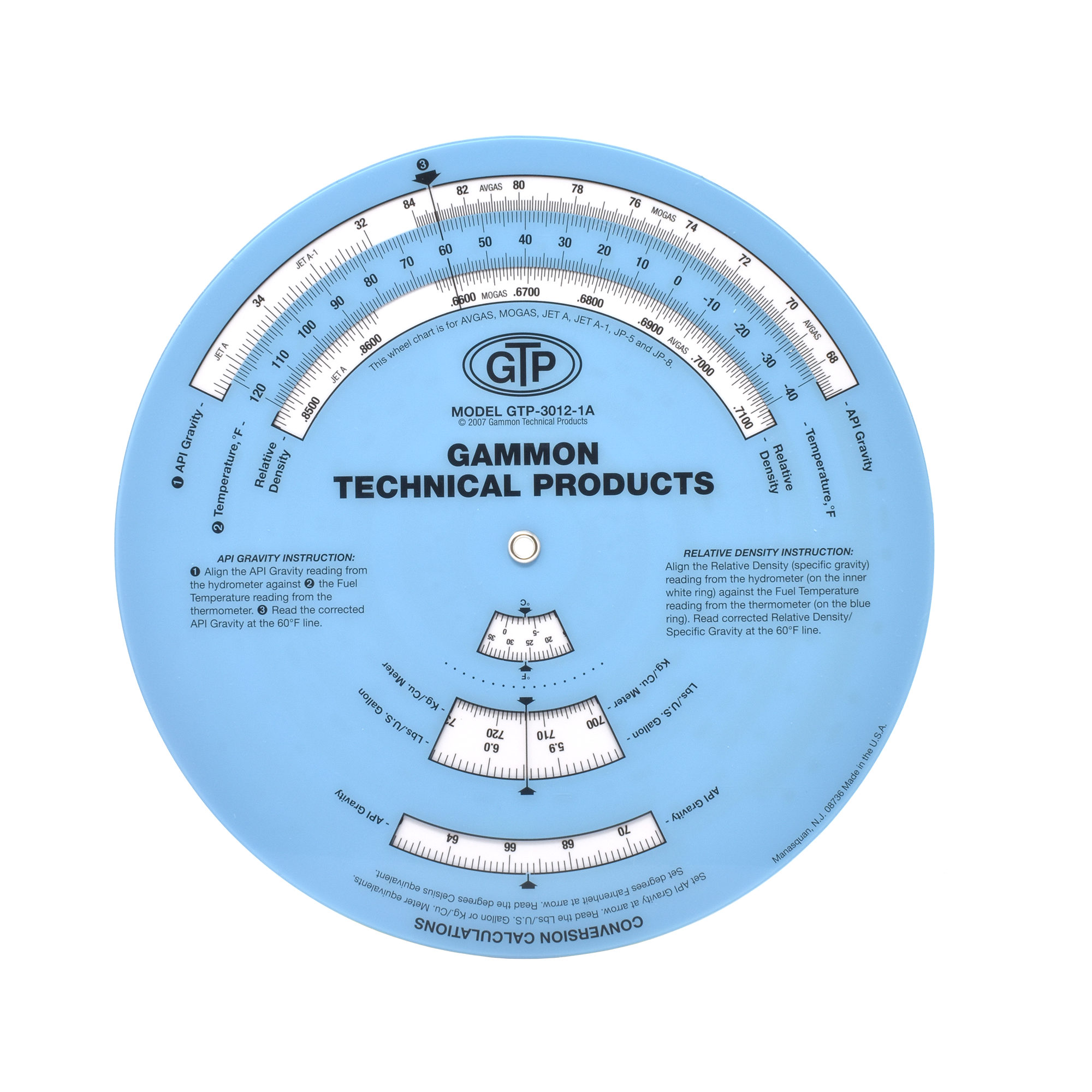
API Gravity Calculator

  • Corrects API hydrometer readings at any temperature (°F) to API degrees at 60°F.

  • Corrects relative density hydrometer readings at any temperature (°F) to relative density at 60°F

  • Converts API gravity to relative density (previously termed specific gravity)

  • Converts API gravity to metric density (kg/m³)

  • Converts API gravity to weight (lbs/gal)

Instructions

  1. Rotate the disk until the observed hydrometer reading (°API) is aligned with observed temperature (°F).
  2. Read the corrected °API at the 60°F arrow.

NOTE: If a relative density or specific gravity hydrometer is used, set the hydrometer reading opposite the observed temperature. Then read the corrected relative density at the 60°F arrow.

Density Calculator

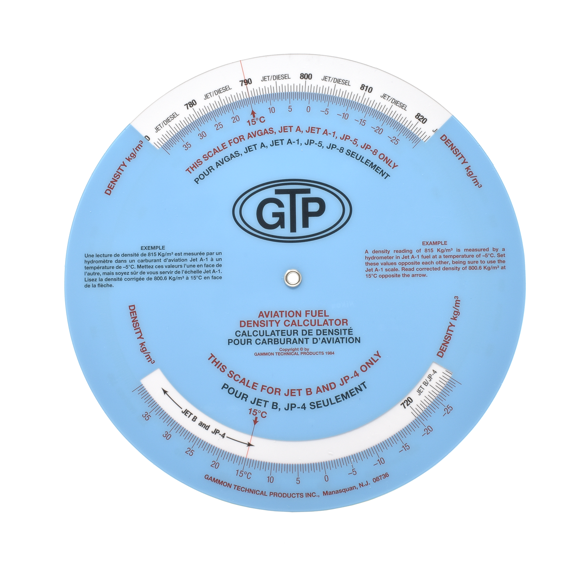
  • Converts density readings taken with a hydrometer to corrected density at 15°C

  • Separate scales for 3 different types of fuel:

    • Kerosene (Jet A, Jet A-1, JP 5, JP 8)
    • Wide Cut (JP 4, Jet B)
    • Avgas
  • Scales read in kg/m³

Instructions

  1. Rotate the disk until the observed hydrometer reading is aligned with observed temperature.
  2. Read the corrected density at the 15°C arrow.

Bulletin 100: API Gravity and Density Calculators2024-10-16T17:08:44+00:00

Bulletin 99: Epoxy-lined Fuel Sample Shipping Containers

NOW REUSABLE

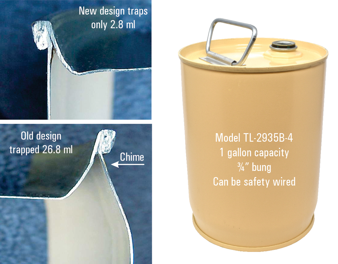
The containers meet UN/1A1/X1.5/250/11 (the last two digits reflect the current year). The UN standard is an international standard equal or superior to DOT 17C and the “250” rating is an improvement over the old container. The bung plug is epoxy coated and can be safety wire sealed. In the photos (below, left), note that when the technician pours fuel from the container, 26.8ml of fuel and dirt particles are trapped in the chime of other containers. Ours traps only 2.8ml.

These containers have been tested in accordance with the approval procedure defined in ASTM Standard Practice D-4306. This standard practice recommends the use of epoxy-lined containers when any of the following ASTM Standard tests are performed on aviation turbine fuels:

  • D-2624 Electrical Conductivity of Aviation and Distillate Fuels
  • D-3241 Thermal Oxidation Stability of Aviation Turbine Fuels (JFTOT Procedure)
  • D-3948 Determining Water Separation Characteristics of Aviation Turbine Fuels by Portable Separameter
  • D-4308 Electrical Conductivity of Liquid Hydrocarbons by Precision Meter
  • D-5001 Measurement of Lubricity of Aviation Turbine Fuels by the Ball-on-Cylinder Lubricity Evaluator (BOCLE)
  • D-5452 Particulate Contamination in Aviation Fuels by Laboratory Filtration
Model No. Capacity Bung Plug Shipping Box
TL-2935B-4 1 gallon 3/4″ TL-2935-2A
TL-2935C-4* 1 gallon 3/4″ TL-2935-2A
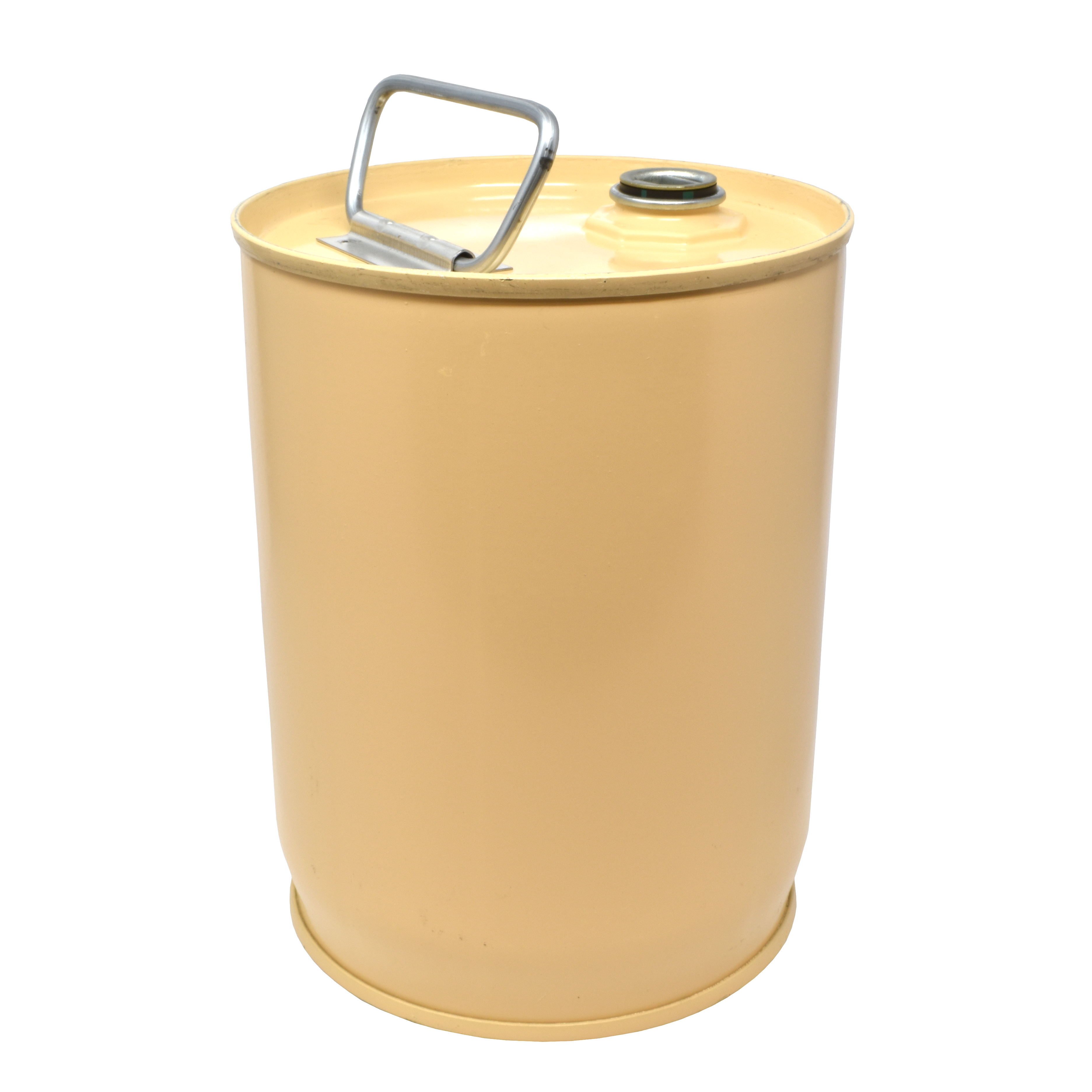
TL-2935A-5 5 gallons 2″ TL-2935-3

* This model has a bung plug that can be safety wired.

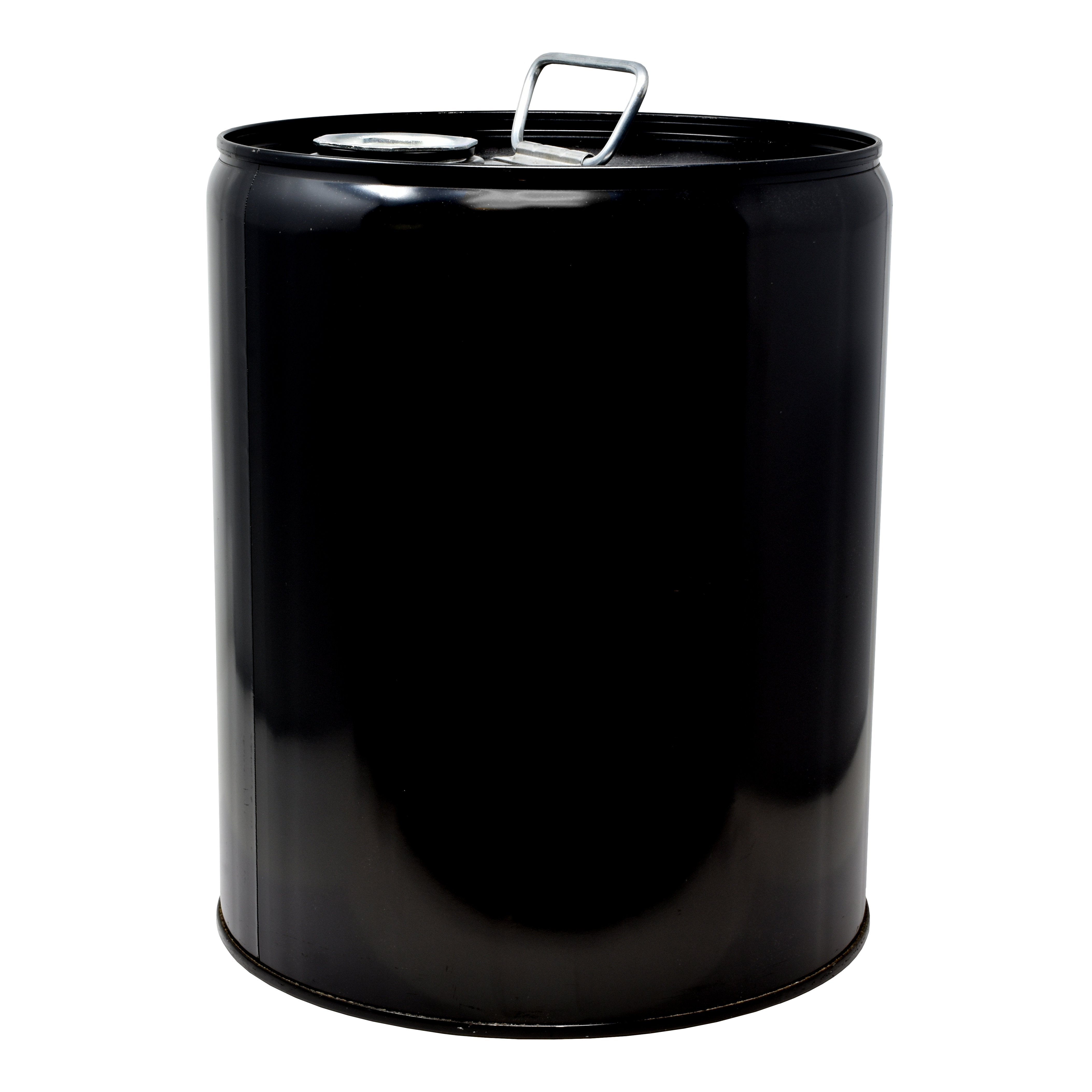
1 gallon can

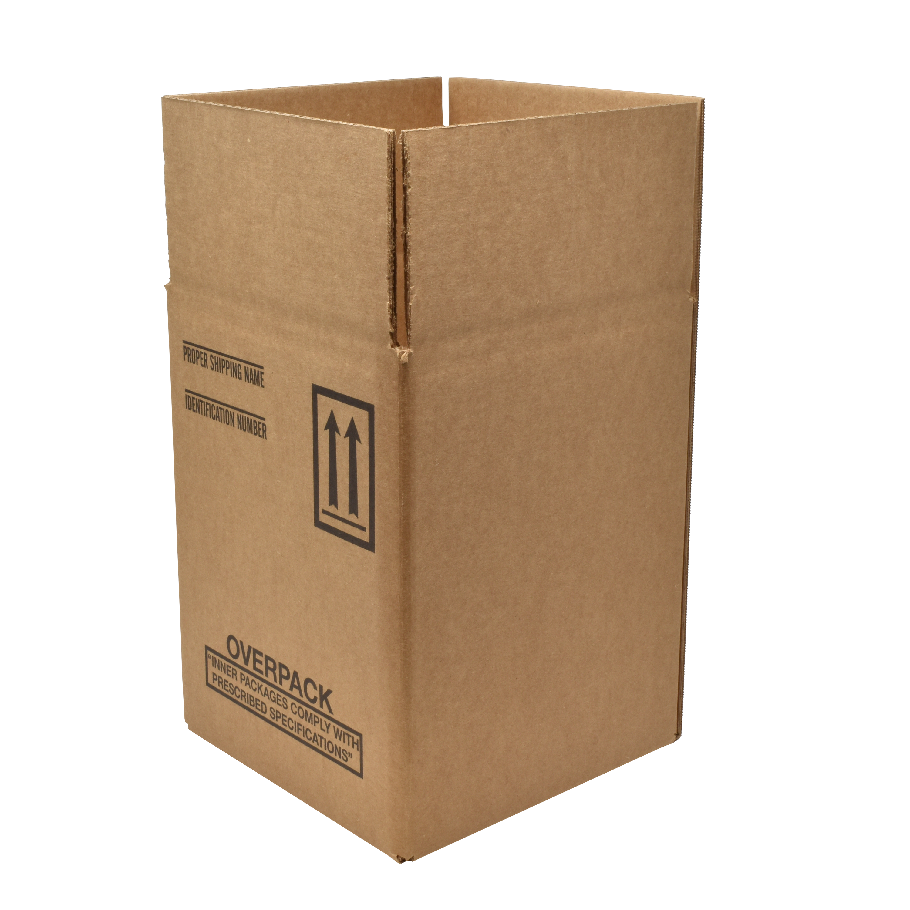
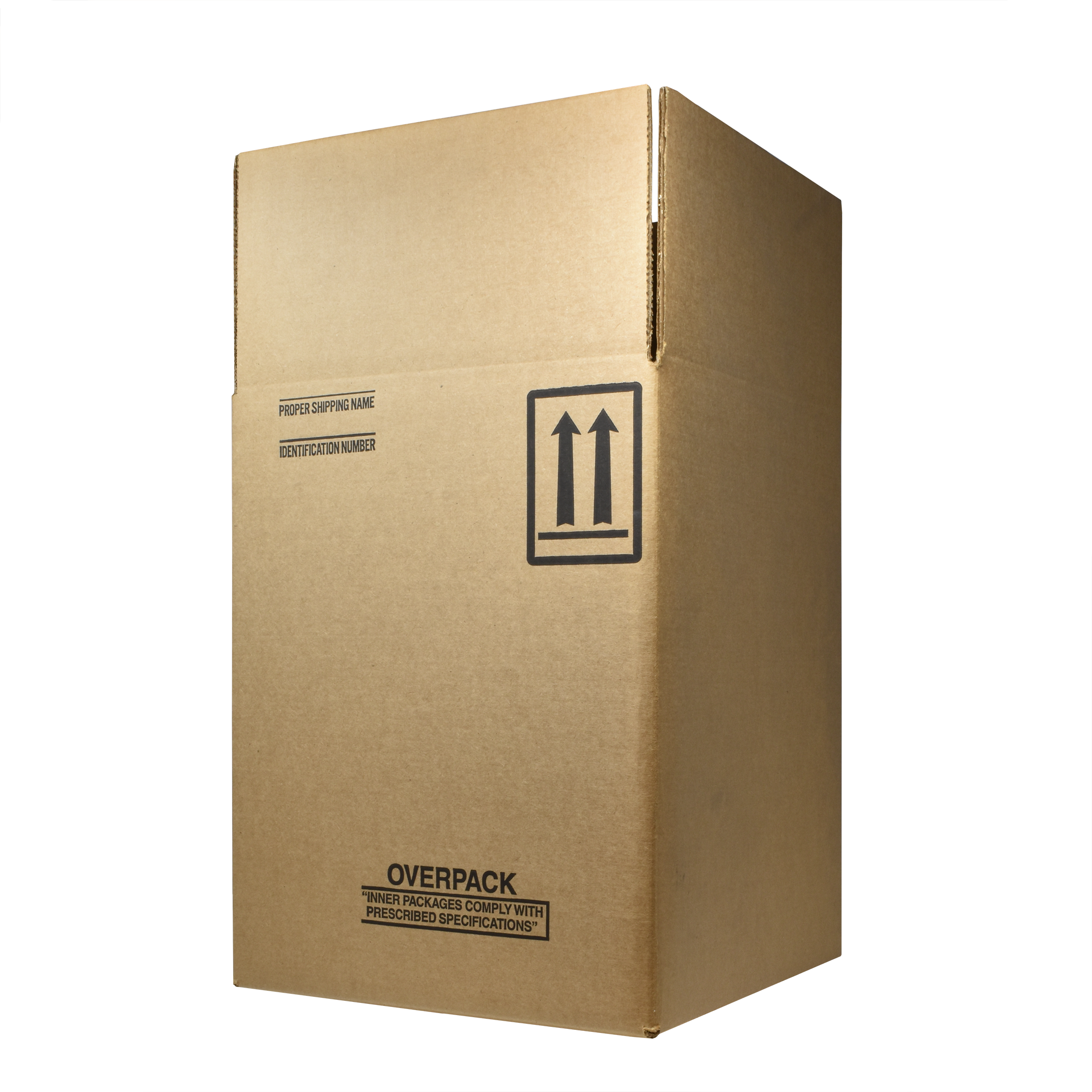
box for 1 gallon can

5 gallon can

box for 5 gallon can

Important Shipping Information

The rules by IATA 1.5 and 49 CFR 172,700 by the U.S. Department of Transportation require that any employee who offers dangerous goods for shipment must be trained in all aspects of packing and labeling. Training courses are offered by many organizations. This bulletin does not purport to provide all the information that is required to prepare and ship fuel samples, but it does show that we offer required decals and labels.

To ship samples of jet fuel or avgas in any of these steel containers, the use of shipping box is required as shown above.

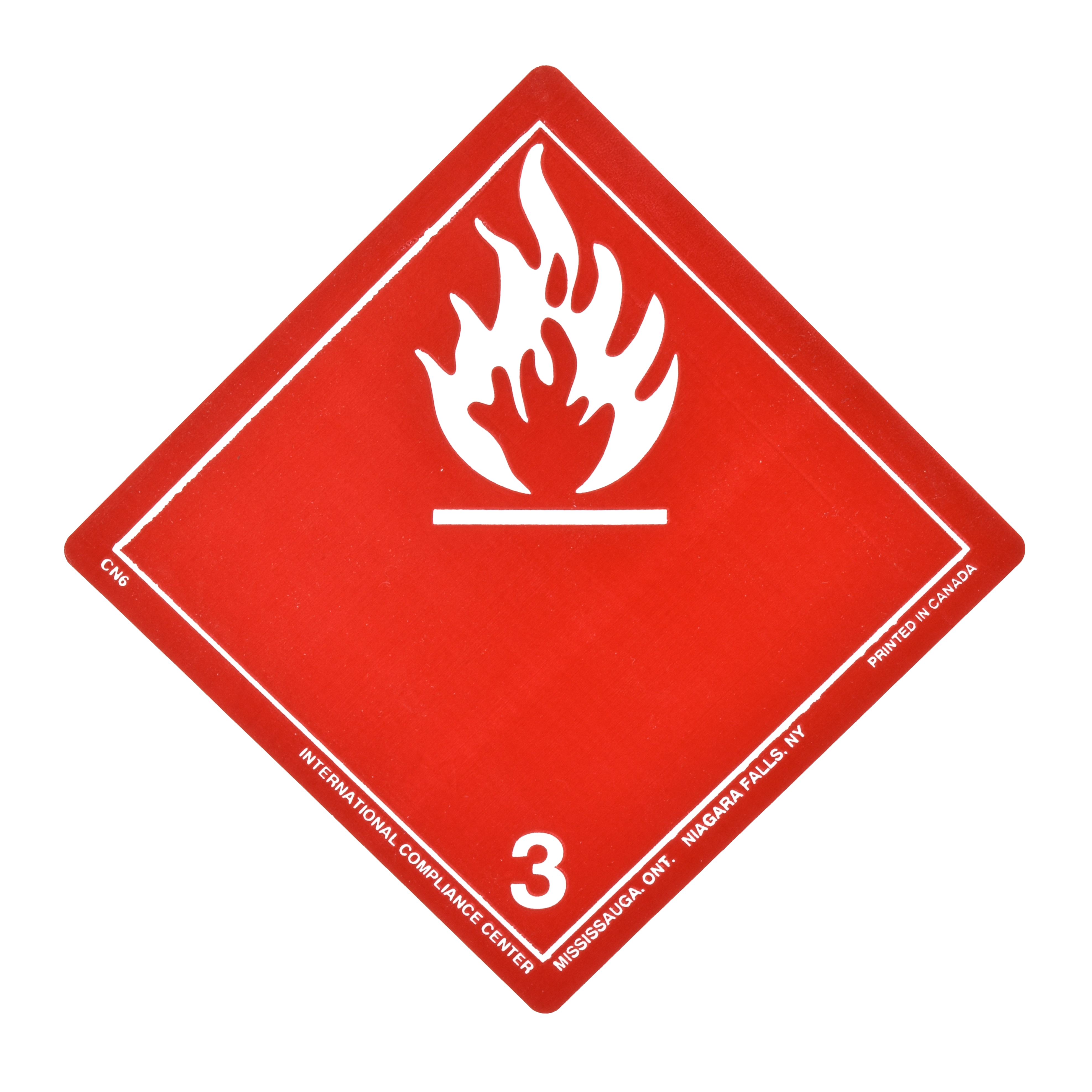
FOR JET FUEL – TL-9050 INCLUDES:

12 x flammable liquid hazard labels

12 x “overpack” labels

24 x package orientation arrows

FOR AVGAS – TL-9051 INCLUDES:

12 x flammable liquid hazard labels

12 x “overpack” labels

24 x package orientation arrows

12 x “cargo aircraft only” labels

Bulletin 99: Epoxy-lined Fuel Sample Shipping Containers2024-10-15T20:38:11+00:00

Bulletin 98: Bonding/Grounding Cable

Grounding/Bonding Cable

We now offer super duty cable in 1/8″ clear and 3/16″ high visibility cable

that lasts three times longer than regular cable.

NOTE: We do NOT offer nylon coatings because we have found that vinyl and Hytrel last longer. The low temperature range for the Hytrel® is -40°F, for the other cable is it -20°F.

Standard Cable

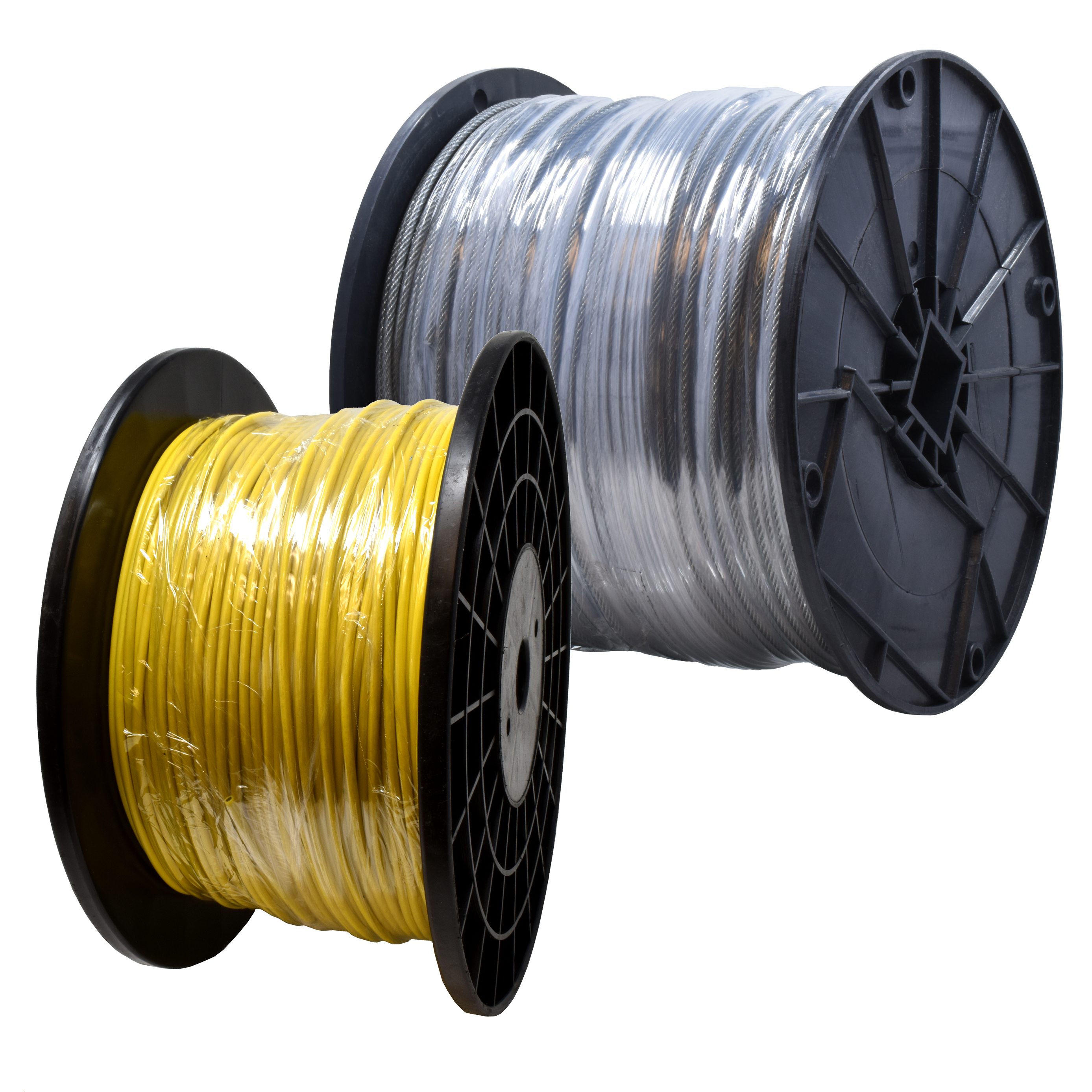
High quality 7×7 galvanized steel cable 3/32” diameter coated to either 1/8” or 3/16” diameter. Available in clear or yellow. Shipped on strong, easy to handle steel or wood spools. The tough vinyl coating also allows great flexibility. Highly conductive.

CLEAR 1/8″ CLEAR 3/16″ PVC YELLOW 5/32″
Cut lengths by foot GTP-1093-1 GTP-1299-1
1000′ reel GTP-1093 GTP-1299 GTP-8557-1

Safety-Orange High Visibility Cable

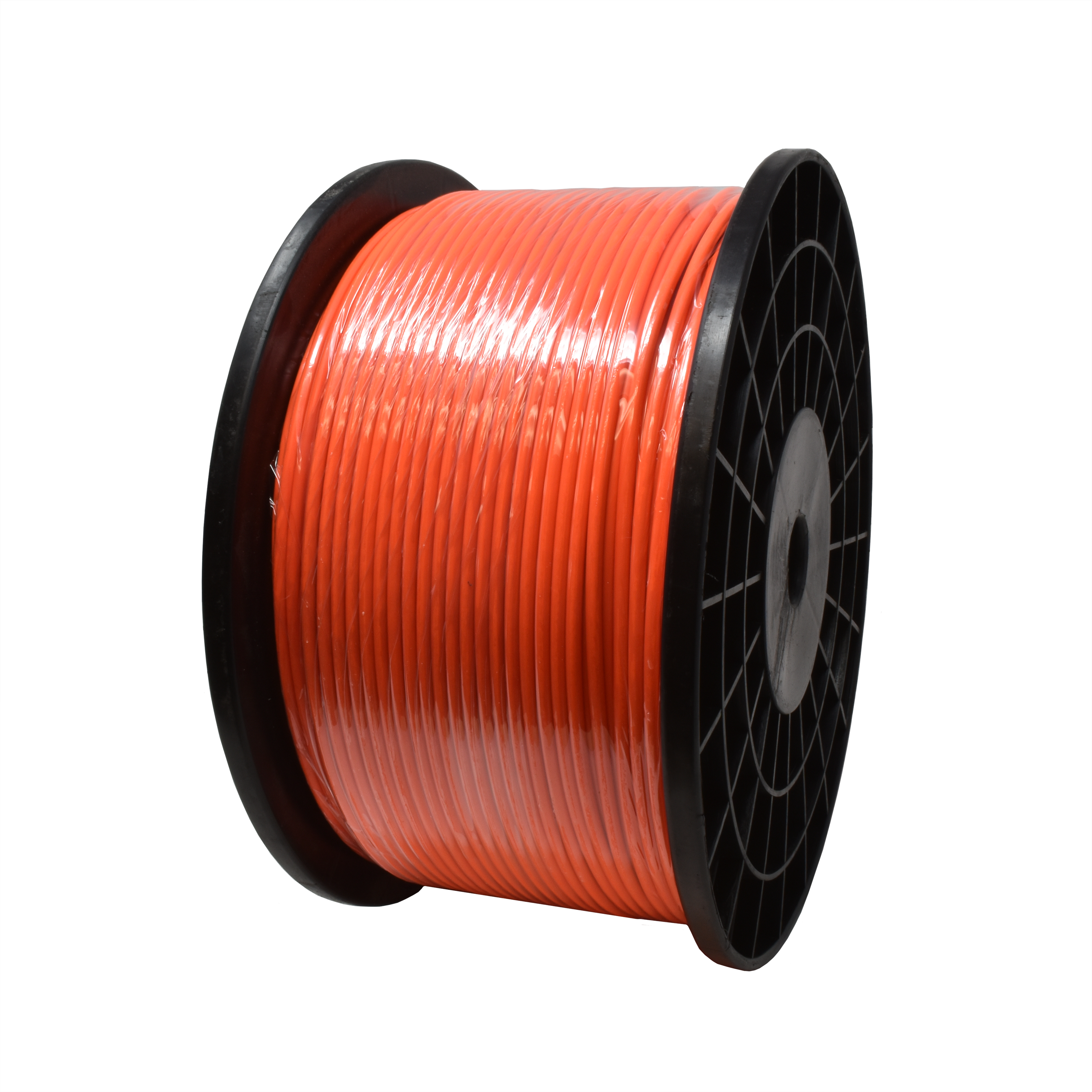
In addition to our standard clear cable, we now offer this high visibility safety-orange cable. This special coating is formulated with a high-tech neon dye which remains visible even in low light. The tough vinyl coating gives long life. This cable is made with our standard 7×7 galvanized steel wire construction, 3/32” coated to 1/8” or 3/16”. Due to our high volume we can offer this cable at a price only slightly higher than our standard clear cable.

1/8″ 3/16″
Cut lengths by foot GTP-1093HVO-1 GTP-1299HVO-1
1000′ reel GTP-1093HVO GTP-1299HVO

Kink Resistant Bright Yellow Cable

You can reduce your problems with kinks and tangles by using this special cable. Resistance to kinking is accomplished by making the cable of specially wound stainless steel instead of galvanized steel. We offer two versions. First, our premium GTP-2869 cable with its oversized 5/32” specially compounded DuPont Hytrel® polyester coating is even tougher than our standard vinyl and the coating adds to the kink resistance of the cable. Resistance to wear and cutting is amazing. For a more affordable cable, we offer cable with 1/8” yellow vinyl coating. This lower-priced cable has the same kink resistant stainless steel cable inside.

HYTREL® 5/32″ VINYL 1/8″
Cut lengths by foot GTP-2869-1 GTP-2869V-1
1000′ reel GTP-2869 GTP-2869V

Bulletin 98: Bonding/Grounding Cable2024-10-15T19:59:14+00:00

Bulletin 92: Pressure Gauges

Pressure Gauges

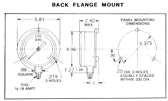
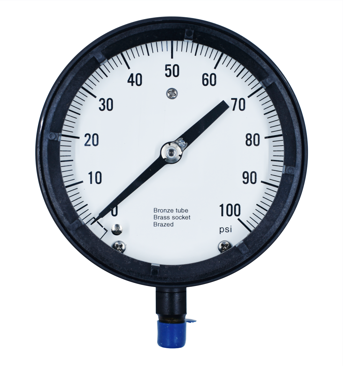
4 1/2″ Face, Back Flange Mounted

Specifications

Case: Cast aluminum with blowout grommet
Bezel ring: Polypropylene, snap-on
Window: Acrylic
Pointer: Slotted hub, adjustable
Bourdon tube: Phosphor bronze
Connection: 1/4″ NPT, brass
Accuracy: 1% of span
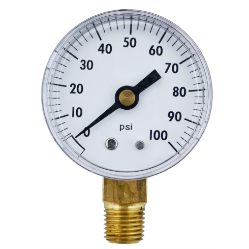
Range: 0-100psi, 0-160psi, or 0-1000psi

2″ and 2 1/2″ Face Pressure Gauges

Specifications

Case: Steel
Bezel ring: Steel
Connection: 1/4″ NPT, brass
Accuracy: 3% of span
Model No. Face Diameter Range, PSI Connection
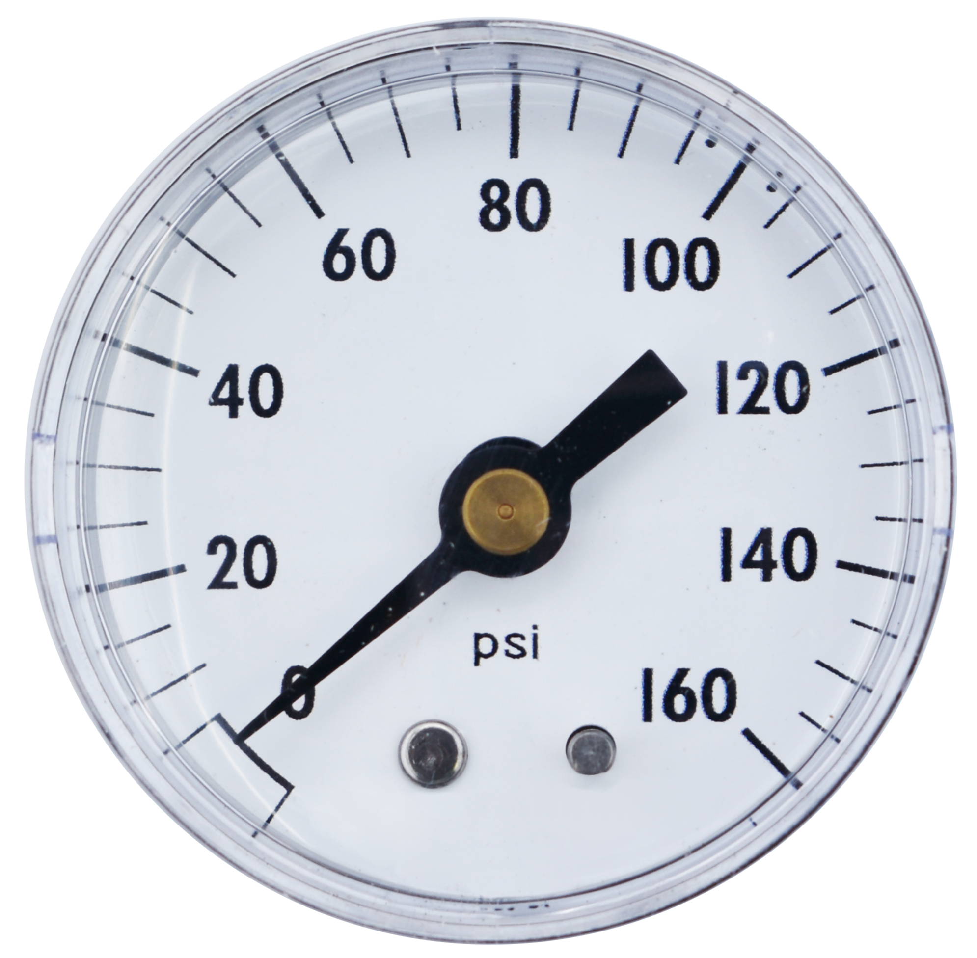
GTP-2954C 2 0-160 Center back
GTP-686A 2 0-60 Lower
GTP-686B 2 0-100 Lower
GTP-686C 2 0-160 Lower
GTP-686D 2 0-300 Lower
GTP-2955C 2 1/2 0-160 Lower

Stainless Steel Stem Mounted

Specifications

Case: Drawn 316 stainless steel
Bezel ring: Drawn stainless steel
Connection: 1/4″ NPT, 316 stainless steel
Accuracy: 1% of span
Model No. Face Diameter Range, PSI
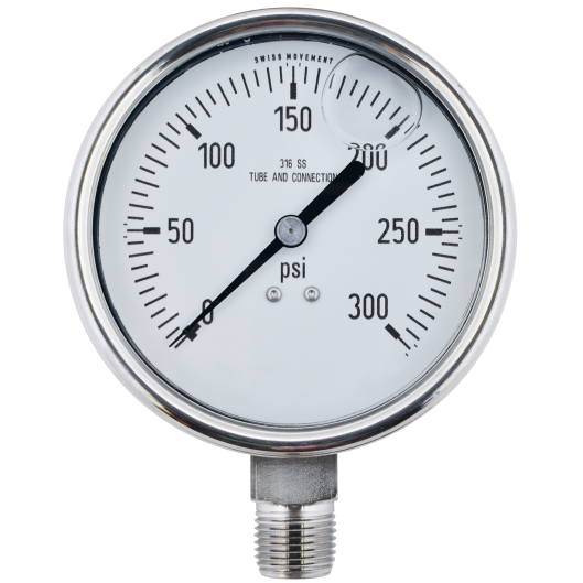
GTP-707D 2 1/2″ 0-300
GTP-2956B 3 1/2 0-100
GTP-2956D 3 1/2 0-300

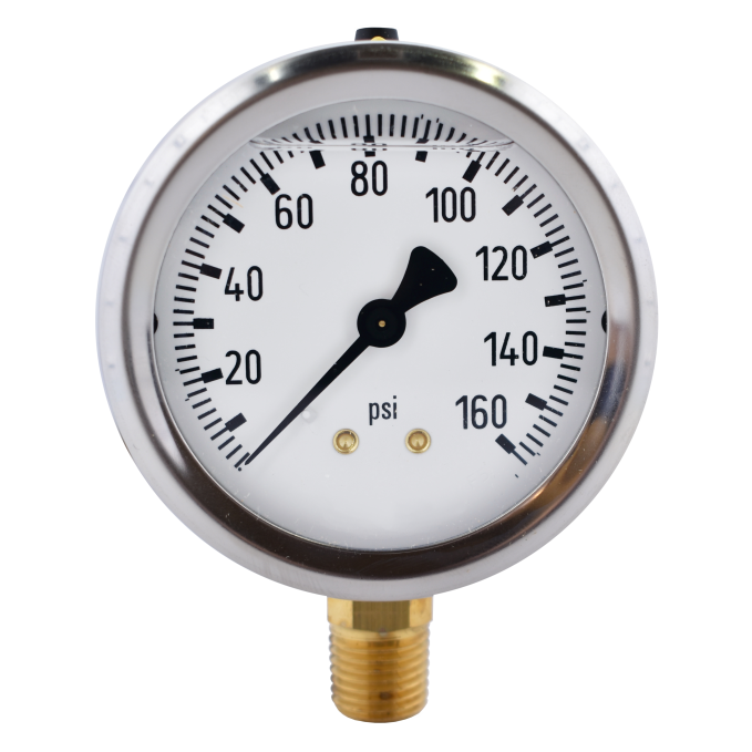
Liquid Filled Pressure Gauges

Steady pointer reading even when pressure is pulsating or in cases of excessive vibration. All are silicone filled.

4″ Diameter

Specifications

Case: Stainless steel
Bezel ring: Steel
Connection: 1/2″ NPT, brass
Mount: Stem mounted
Accuracy: ±1% of span
Model No. Range, PSI
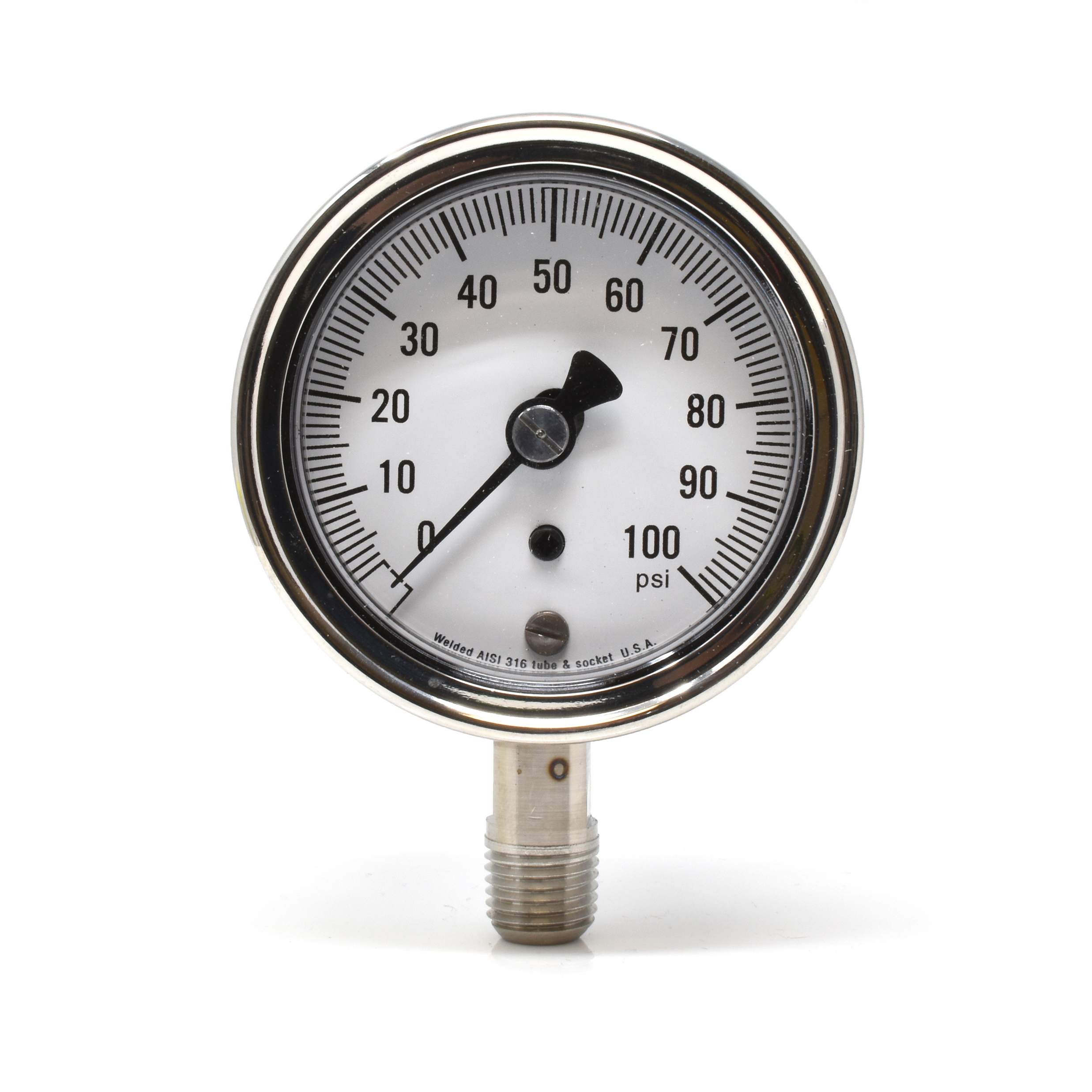
GTP-5866 0-100
GTP-5867 0-160
GTP-5868 0-300

2 1/2″ Diameter

Specifications

Case: Stainless steel
Bezel ring: Steel
Connection: 1/2″ NPT, brass
Mount: Stem mounted
Accuracy: ±1% of span
Model No. Range, PSI Connection
GTP-5873 0-100 Brass/bronze
GTP-5874 0-100 316 stainless steel
GTP-5875 0-160 Brass/bronze
GTP-5876 0-160 316 stainless steel

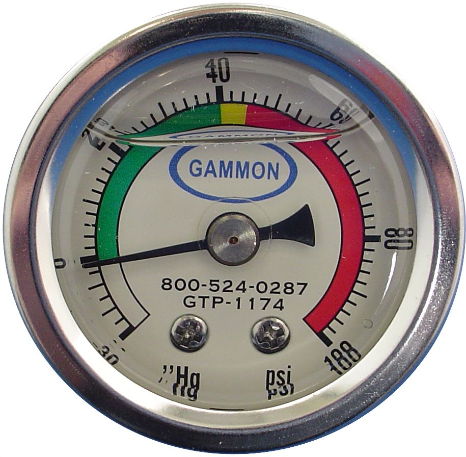
1 1/2″ Diameter

Specifications

Case: Steel
Bezel ring: Steel
Connection: 1/8″ NPT, brass
Mount: Center back
Accuracy: ±3% of span
Model No. Range, PSI
GTP-1174 0-100

Bulletin 92: Pressure Gauges2024-10-11T17:31:49+00:00

Bulletin 87: “Q” Kit Jet Fuel Quality Control

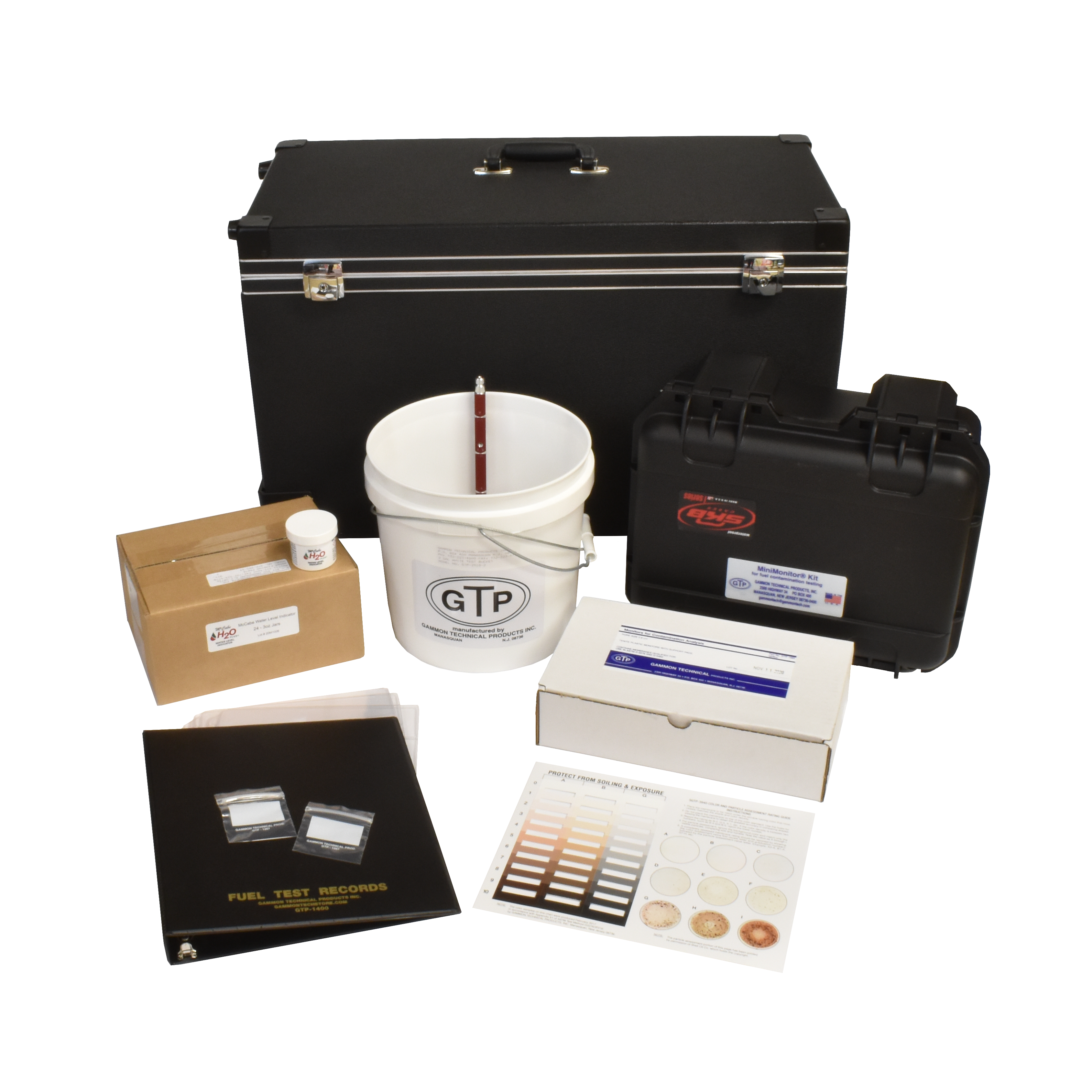
The Gammon “Q” Kit

GTP-2652-1 (2 gallon) and GTP-2652-2 (5 gallon)

A basic self-contained package for the fixed base operator, fueling contractor or private carrier who must perform safety checks on jet fuel. Everything needed to determine the presence of solid contaminants and excess water is packaged together for carrying convenience and safe-keeping in a case with handle and lock. The new and improved case features a telescopic handle and wheels.

Features

  • The Gammon MiniMonitor® Kit for containment testing per ASTM D2176, including electrostatic bonding and grounding discharge hose assembly

  • Special tweezers designed for handling delicate filter membranes

  • Color rating book meeting ASTM Method D2176

  • White bucket – 2 or 5 gallon capacity – including grounding rod and level indicator

  • Supply of 48 plastic monitors pre-packaged with filter membranes and support pads

  • Complete record-keeping system featuring filing envelopes with write-on panels, filing pages with pockets, and a notebook binder for record-keeping

  • Long-term supply of water-finding paste

Included in the “Q” Kit

Part Number Description
GTP-172 MiniMonitor Kit
GTP-1985 monitors, box of 48
GTP-1400 notebook
GTP-1331 filing pages, set of 10
GTP-2099 tweezers
GTP-1267 envelopes, package of 500
GTP-982-12 water finding paste, 12 jars
GTP-2651-1 case, 26″ x 12.5″ x 15″
GTP-2518-2
OR
GTP-2518-5
2-gallon white bucket
OR
5-gallon white bucket

Bulletin 87: “Q” Kit Jet Fuel Quality Control2024-10-09T13:42:11+00:00

Bulletin 86: Aqua-Glo® Water Detector

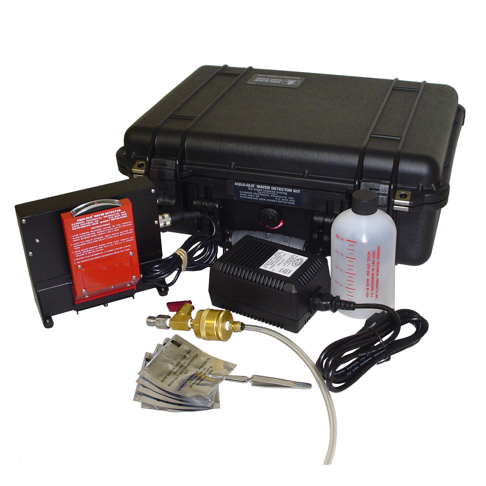
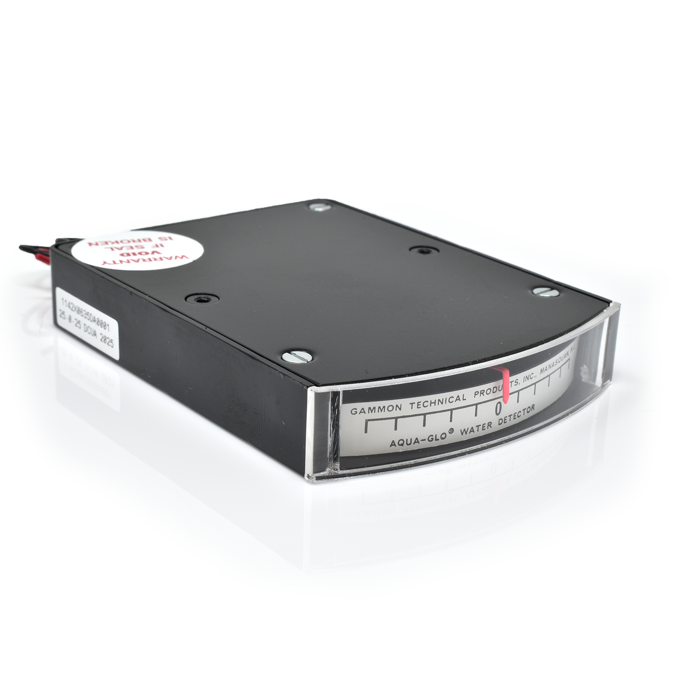
The Aqua-Glo®

measures water content of jet fuel

Features

  • Manufactured specifically to perform tests per ASTM Method D3240

  • Automatic power switching between external power supply and internal battery 120/220 volts, 50-60 Hz

  • Nickel cadmium rechargeable battery

  • Fully instrumented to eliminate human error

  • Detects presence of free water within 1.5 ppm

  • Test completed in less than 2 minutes

  • Portable, lightweight (8 pounds)

  • Permanent fluorescing standard will not deteriorate with age

  • Can be recalibrated in the field

The test requires two simple steps. First, a measured sample of fuel is passed through a paper pad that is treated with sodium fluorescein on its upstream surface. Second, the pad is compared with a fluorescing standard in ultraviolet light. Water droplets that are smaller than the eye can see will cause the sodium fluorescein to fluoresce. The degree of fluorescence is greater for increasing amounts of water in the fuel.

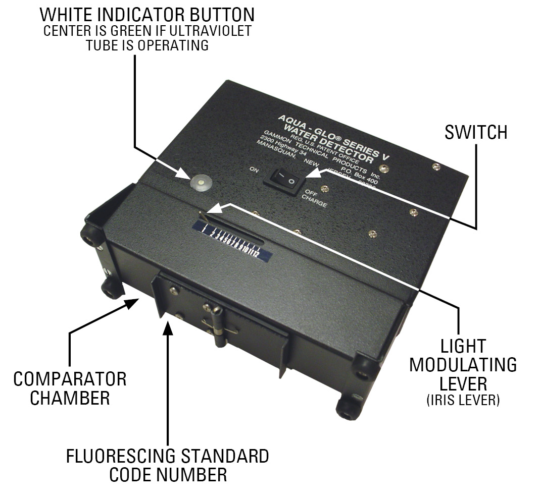
The Aqua-Glo® Kit employs this unique approach in the determination of the degree of fluorescence (or water content). A single, permanent fluorescing standard is positioned under a photographic-type iris diaphragm which can be opened or closed to increase or decrease the amount of ultraviolet light.

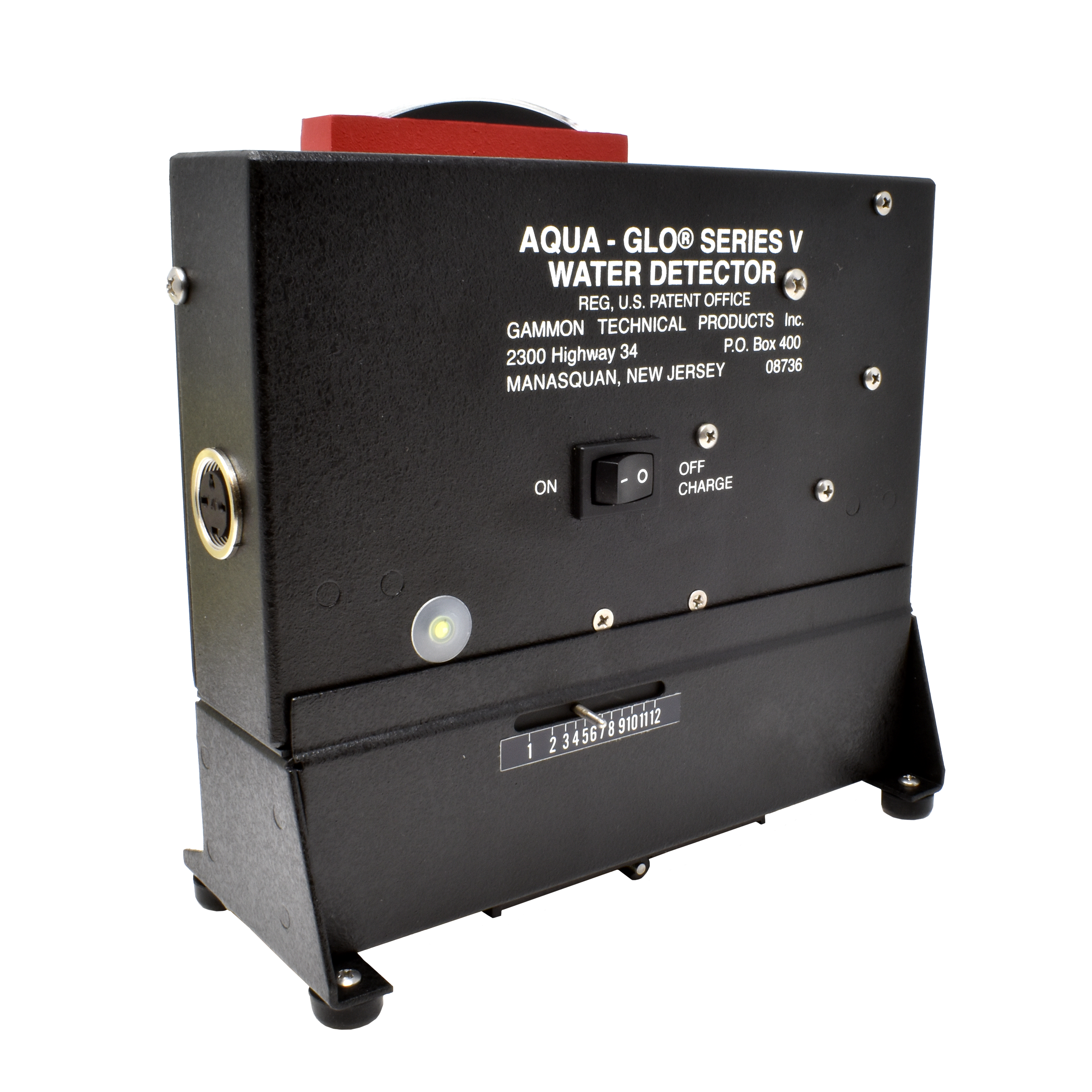
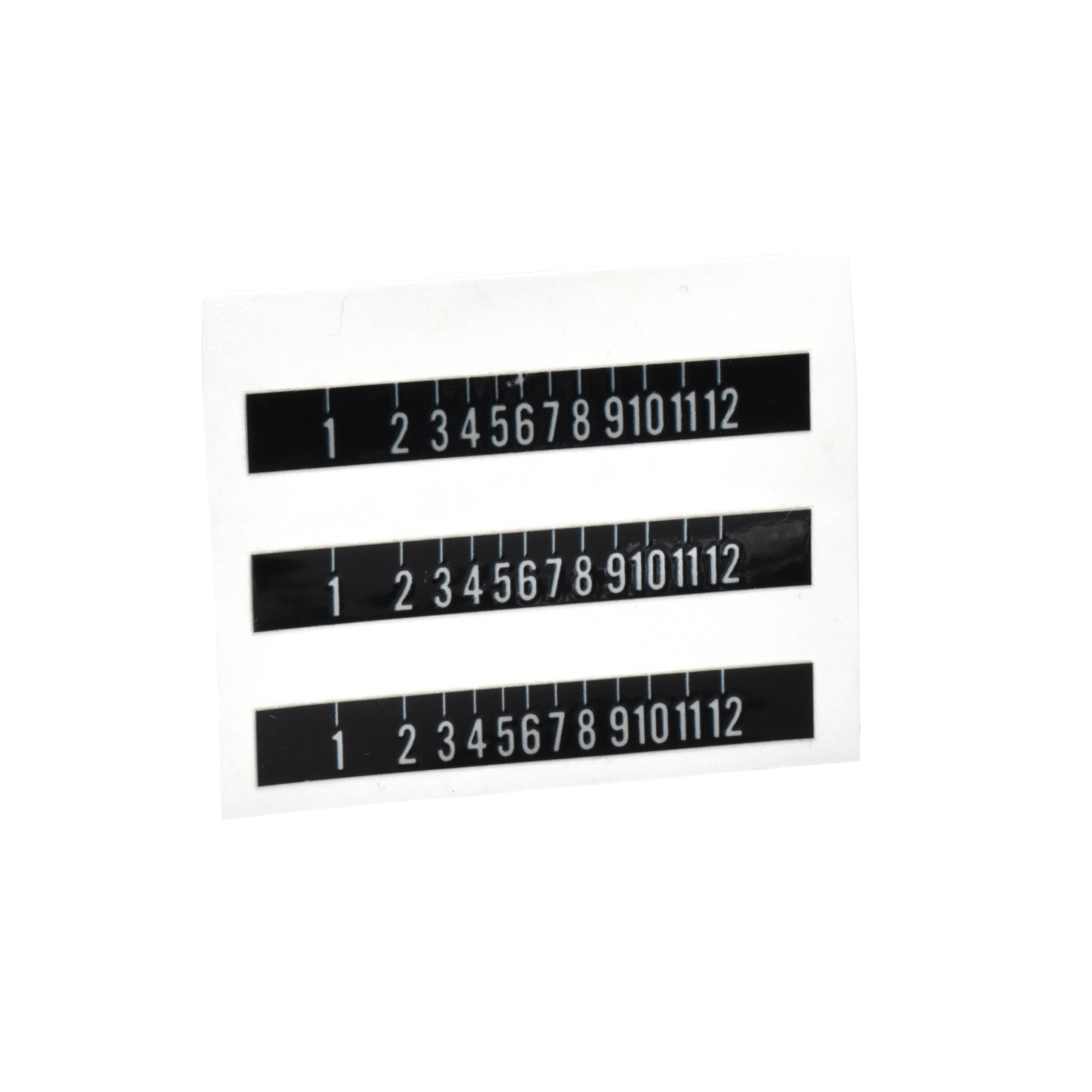
To determine water content, the operator merely adjusts the diaphragm lever arm under the fluorescing standard and the test pad show equal brightness in the ultraviolet light. This balance is reached when the zero centering ammeter reads ZERO. The amount of water is read in parts per million (ppm) on the diaphragm lever arm scale which has been pre-calibrated in the factory. The scale numbers range from 1 to 12. These numbers are in ppm if the test sample of fuel that flowed through the pad was 500 ml. However, if water content is as great as 60 ppm, the test sample can be reduced to 100 ml. When a 100 ml sample is taken, the operating instructions explain that the scale reading must be multiplied by 5 to obtain the water content in ppm.

The Series V Aqua-Glo® was introduced in 2005 with an entirely new power supply. This power supply is external, automatically switching to work with either 120 VAC or 220 VAC, 50/60 Hz.

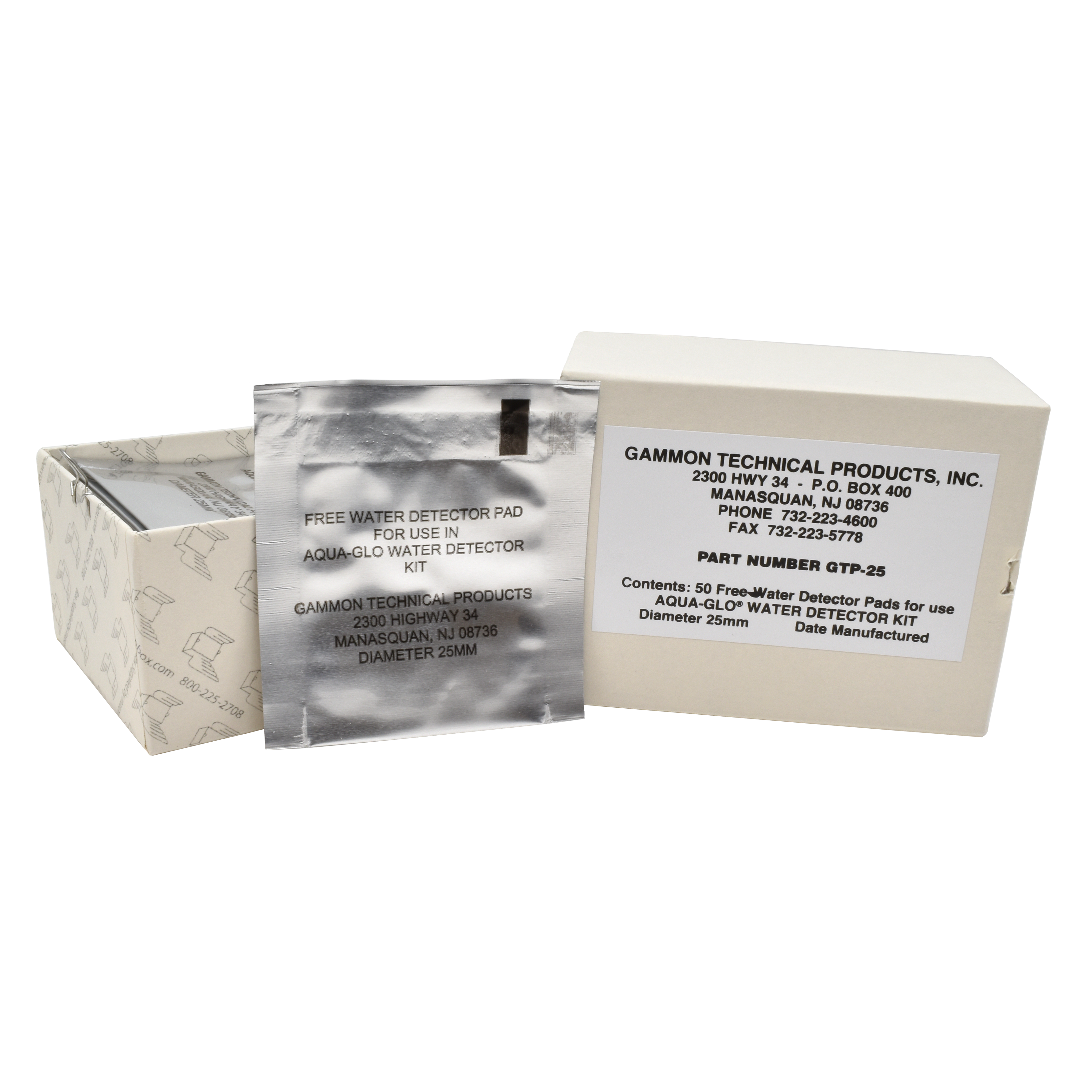
The water detector pads that are used in the Aqua-Glo® Kit are produced in compliance with MIL-D-81248 (WP) with the exception that the diameter is 25mm. Each pad is packaged in an air and moisture-proof envelope.

The Aqua-Glo® Kit pad holder is designed for ease in sampling. Fittings are available for several different methods of taking samples. For example, the standard fitting permits direct connection to the quick disconnect. Another fitting allows the sample to be drawn through the test pad with a syringe.

The Aqua-Glo® Kit is based on a technique developed by the U.S. Navy for accurate field determination of the free water content of jet fuels. Unlike the Navy equipment, the Aqua-Glo® Kit requires only one fluorescing standard and is instrumented to eliminate human error.

Available also in combination with our MiniMonitor® Kit for contamination testing per ASTM Method D2276.

See Bulletin 8 for details on the MiniMonitor® Kit.

How to Order

Kits

GTP-322
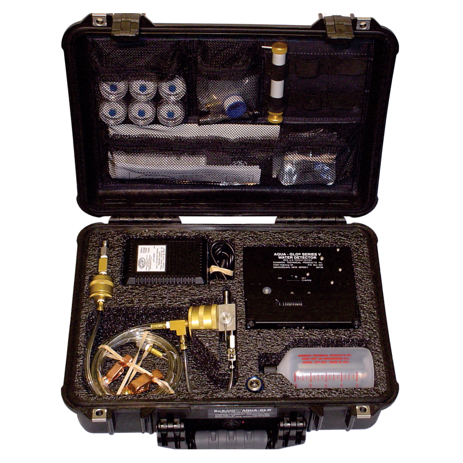
Aqua-Glo® Series V Kit with built-in 120/220 VAC 50-60 Hz power supply

GTP-323
Combination Kit: Aqua-Glo® Series V and MiniMonitor® with 120/220 VAC 50-60 Hz power supply

GTP-2855
Aqua-Glo® unit only with power supply and standards, 120/220 VAC

Parts & Accessories

GTP-25
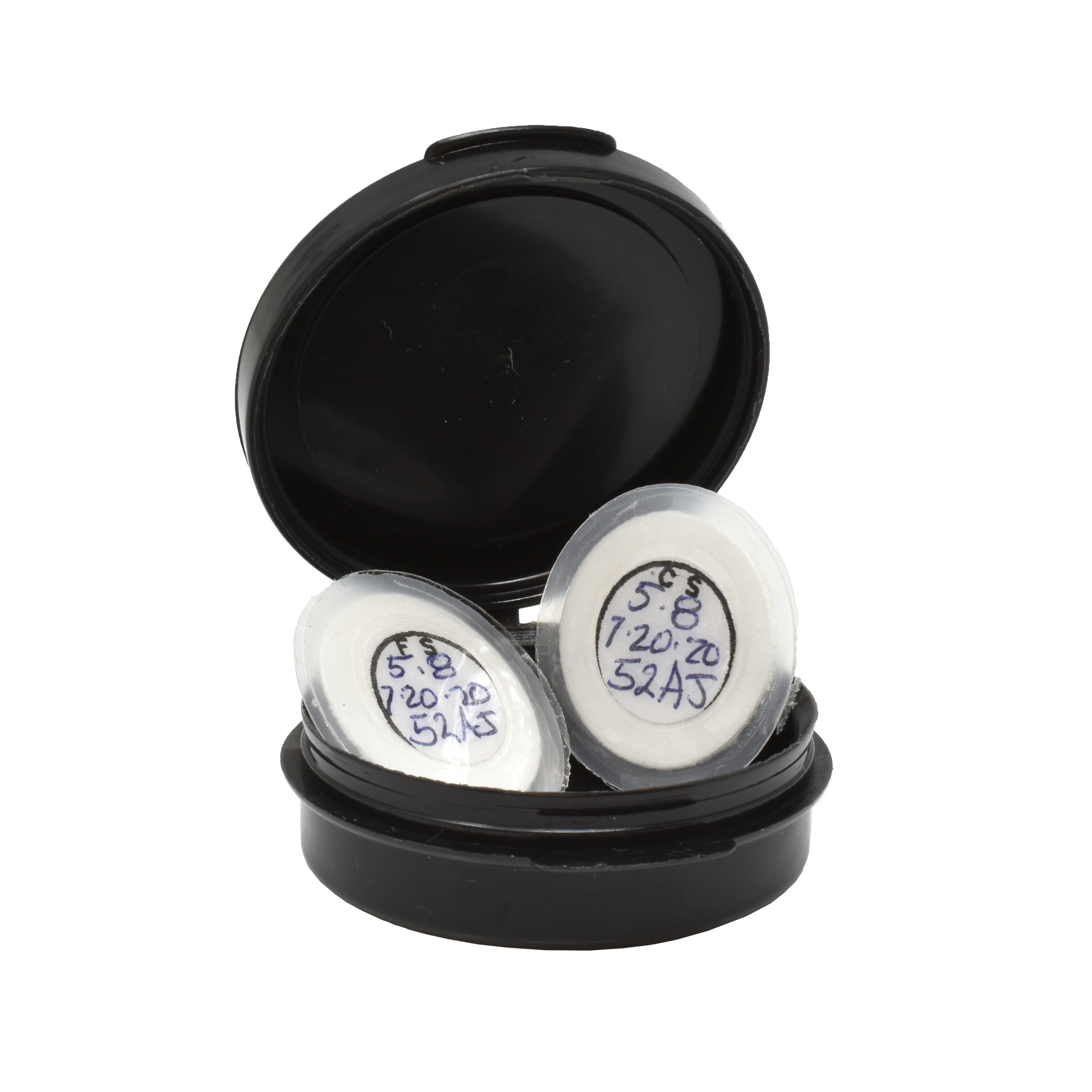
water detector pads (25mm diameter), box of 50

GTP-2324
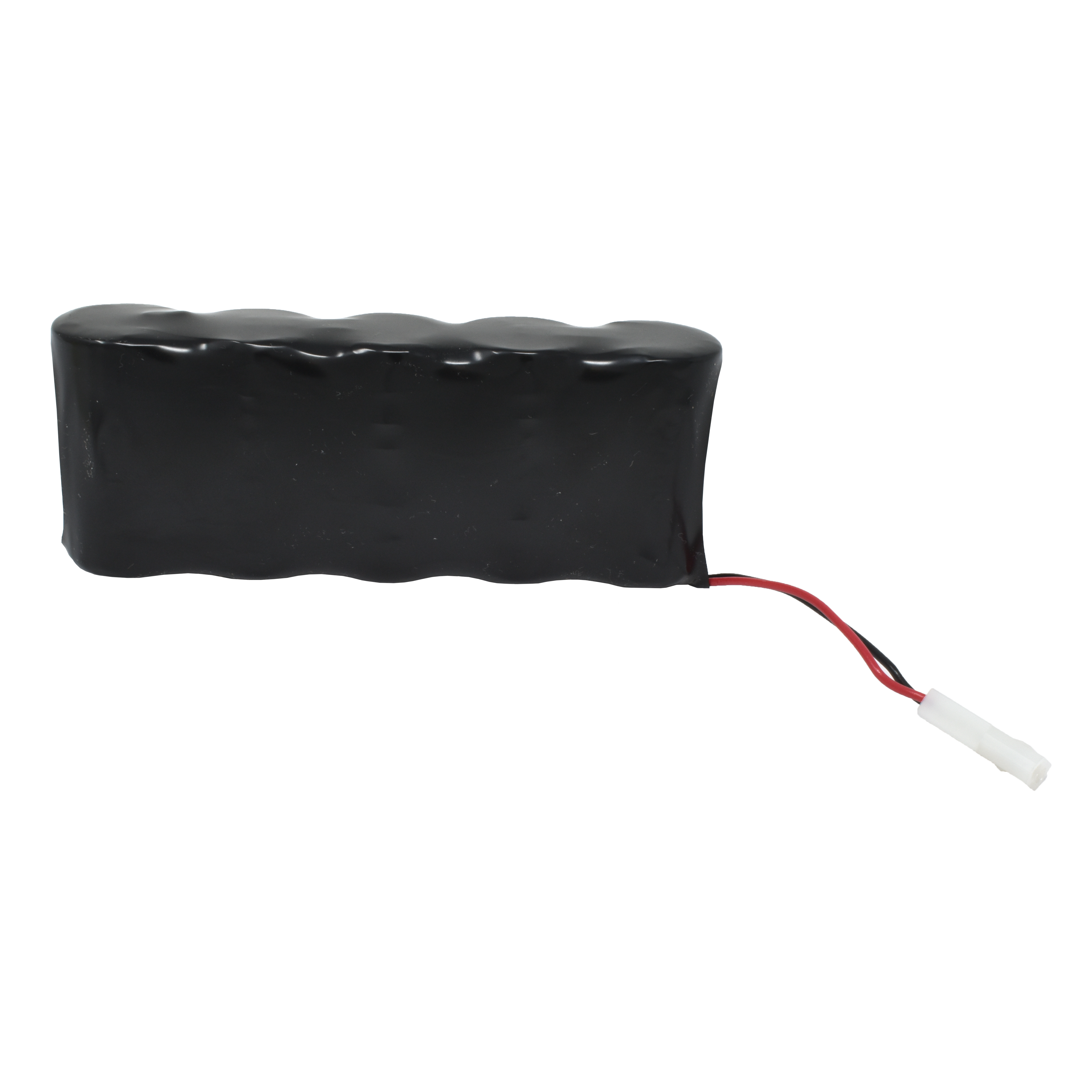
internal/external battery, rechargeable, nickel cadmium

GTP-2380
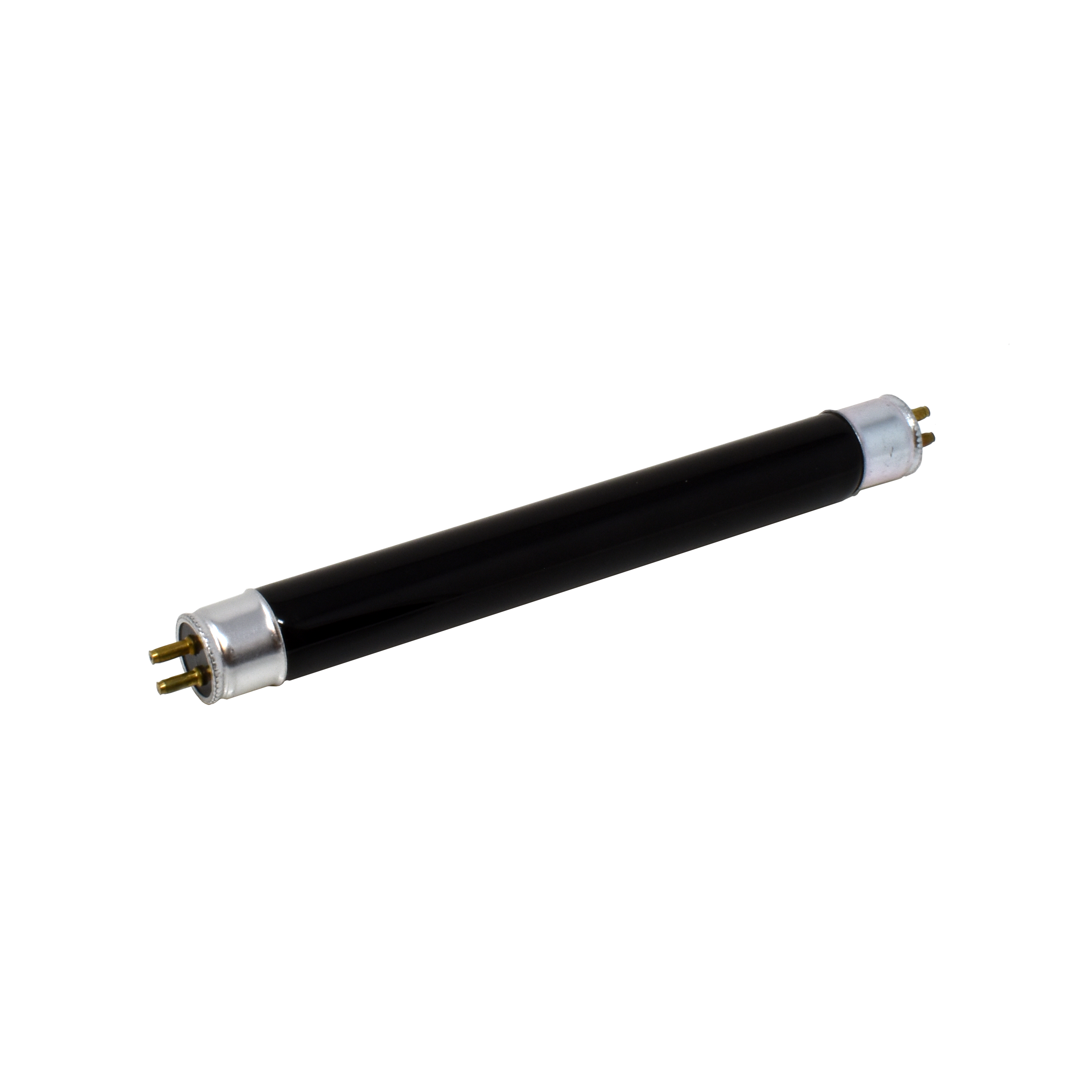
replacement ultraviolet tube

GTP-191
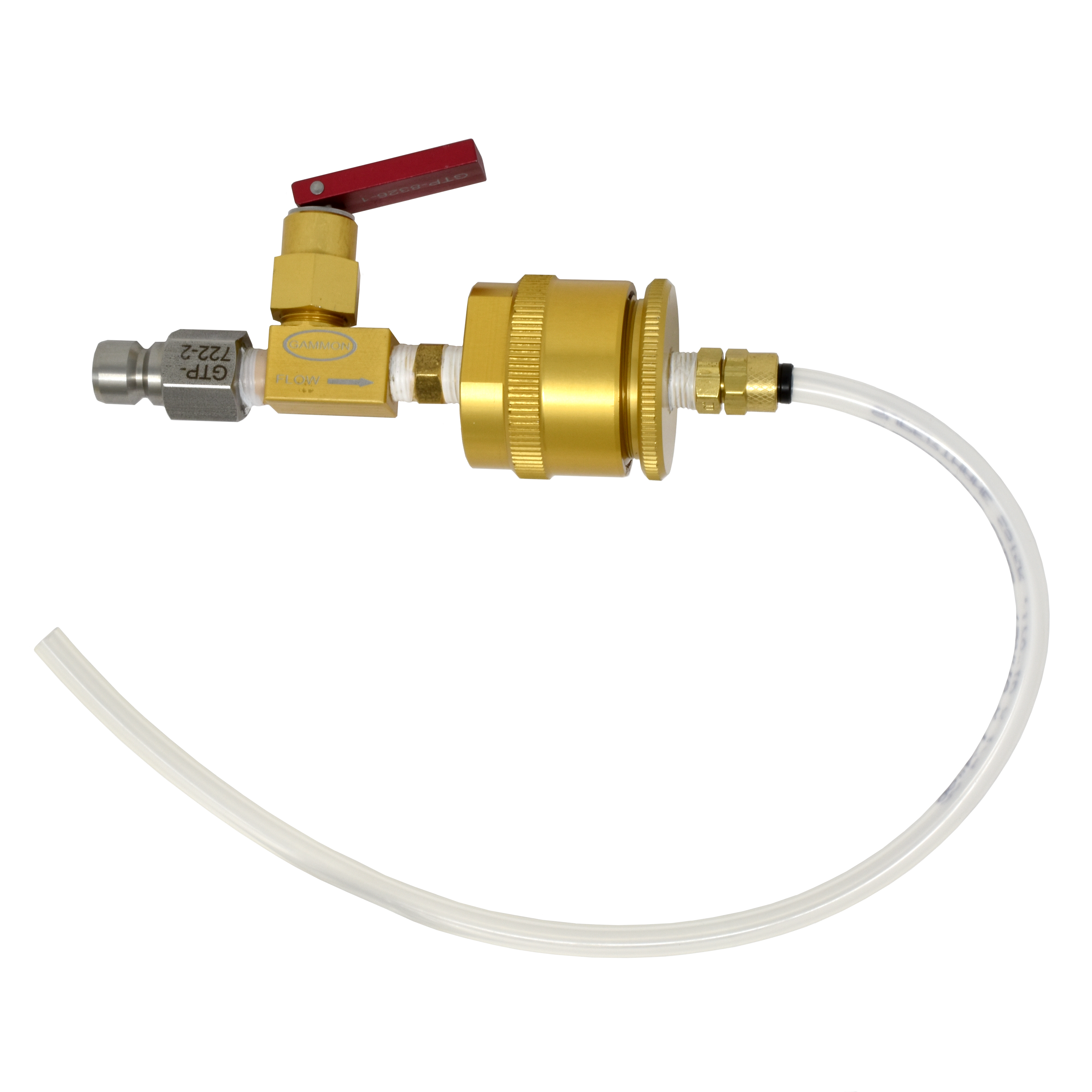
detector pad holder assembly

GTP-8326-1
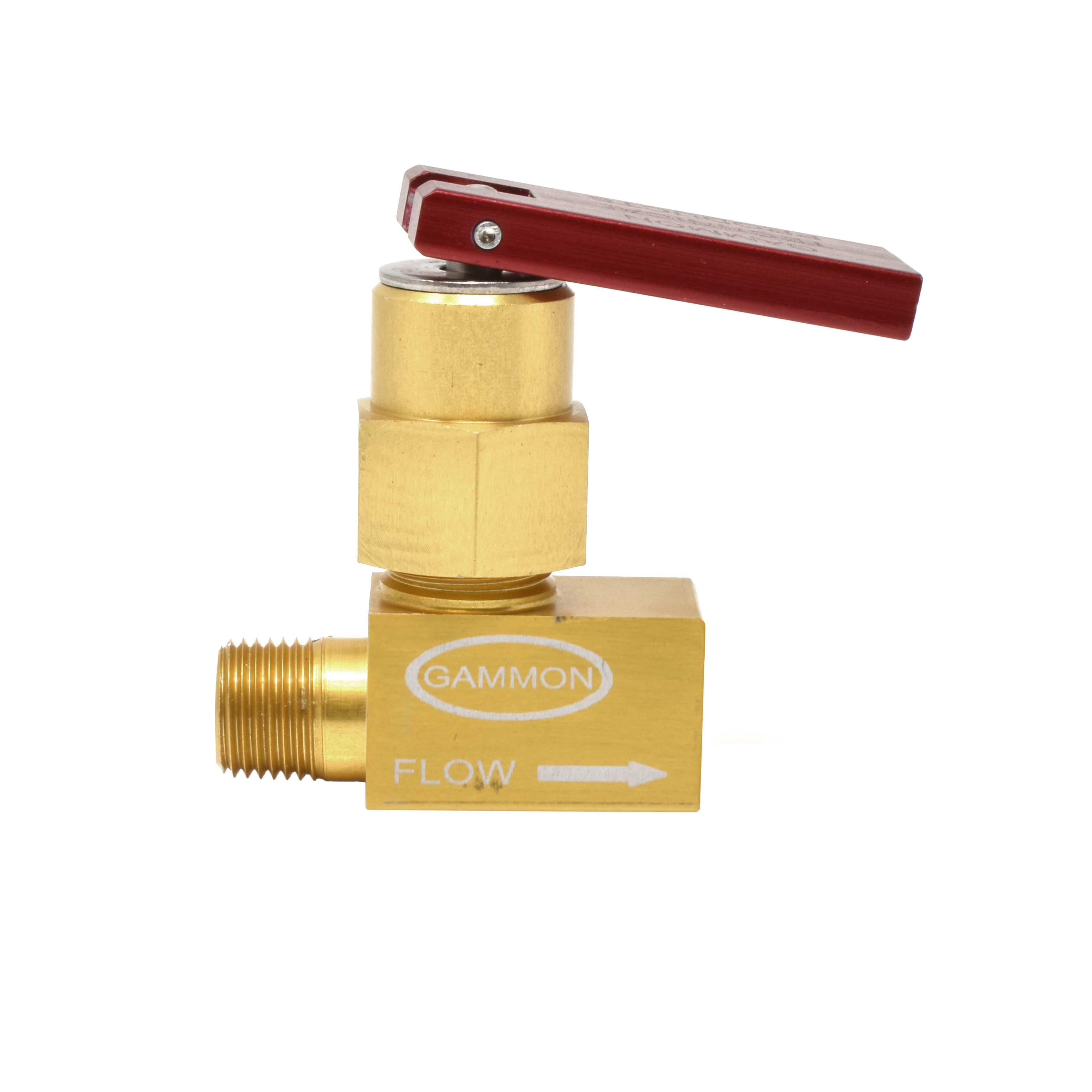
toggle valve, aluminum, 1/8″ FNPT

GTP-293
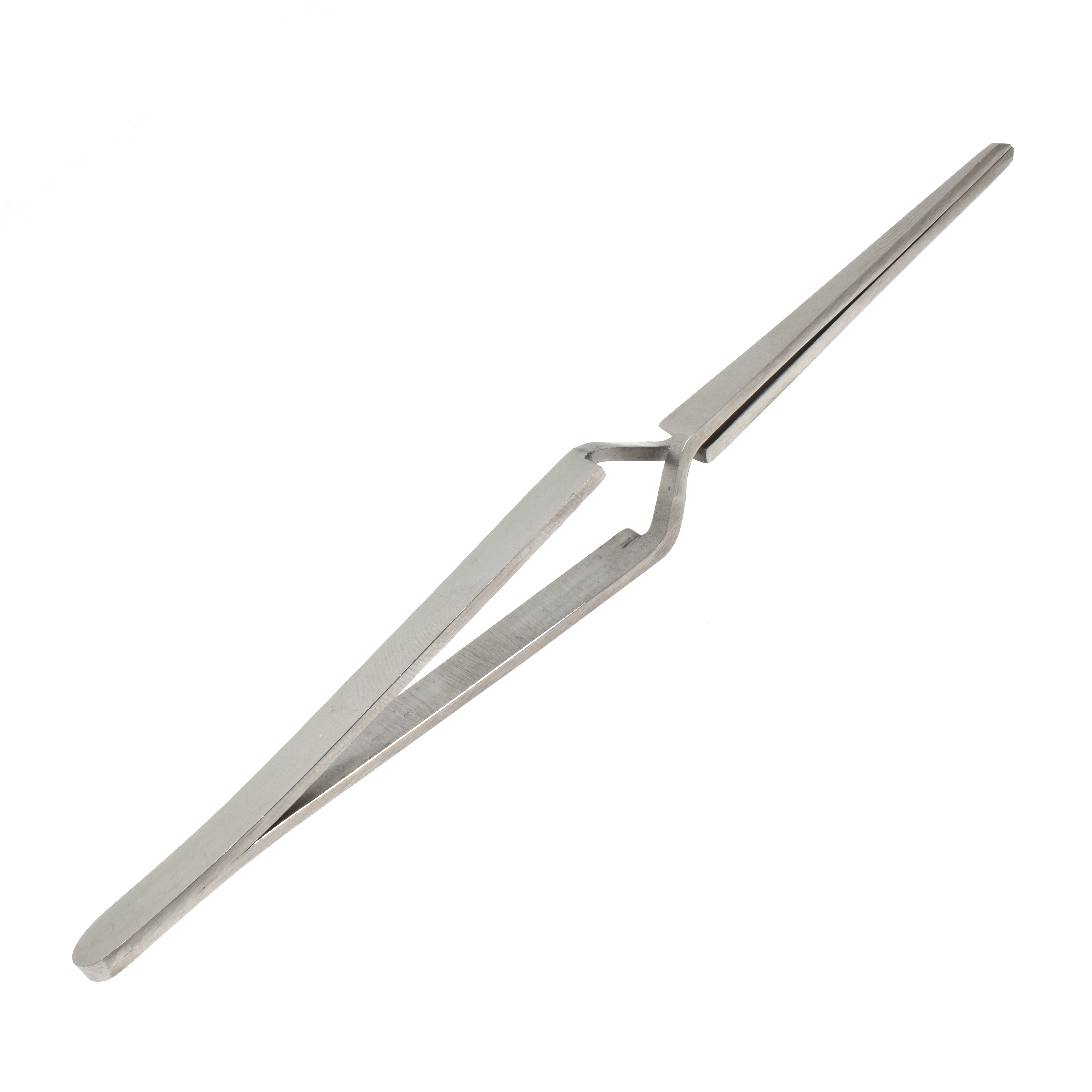
tweezers

GTP-294
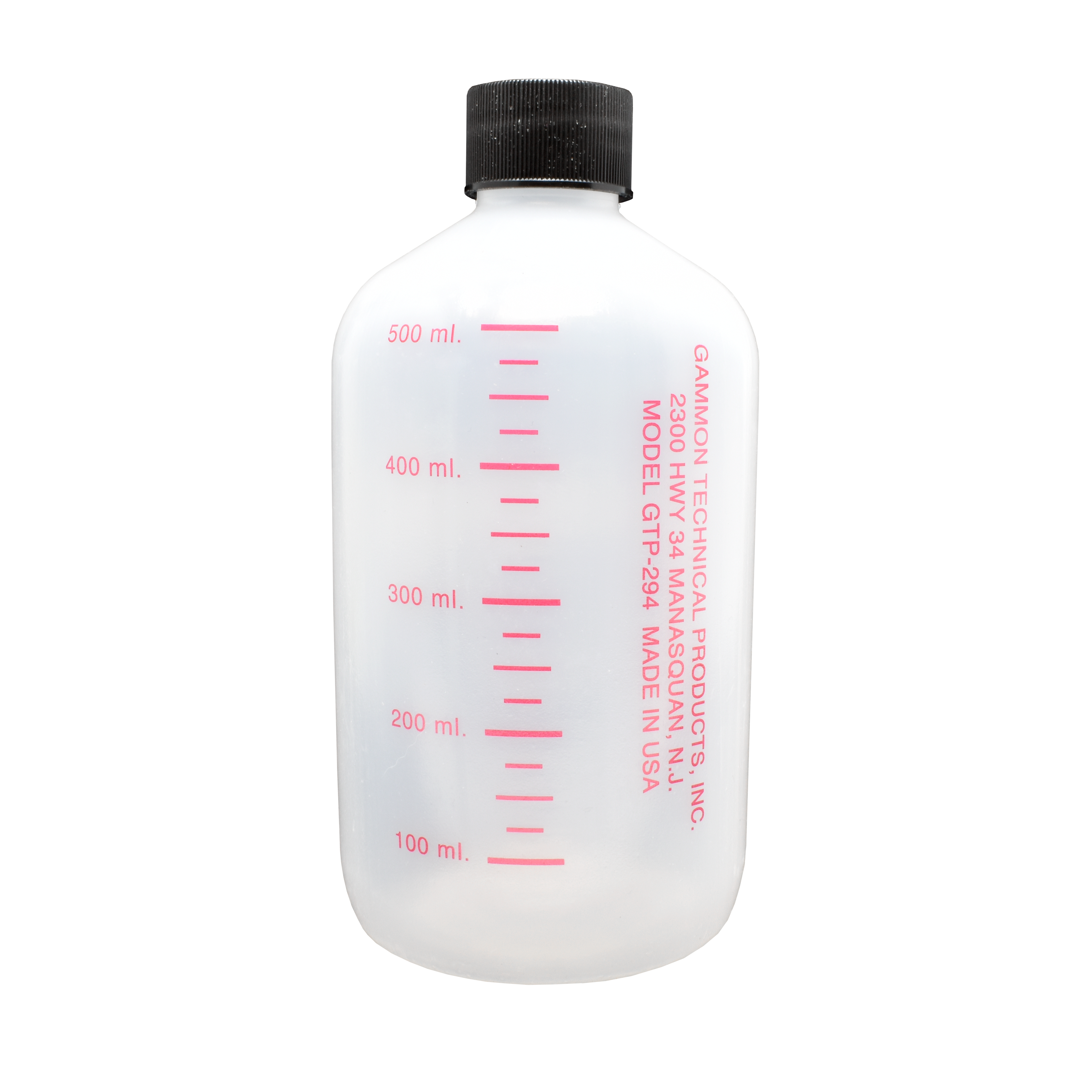
calibrated bottle

GTP-765
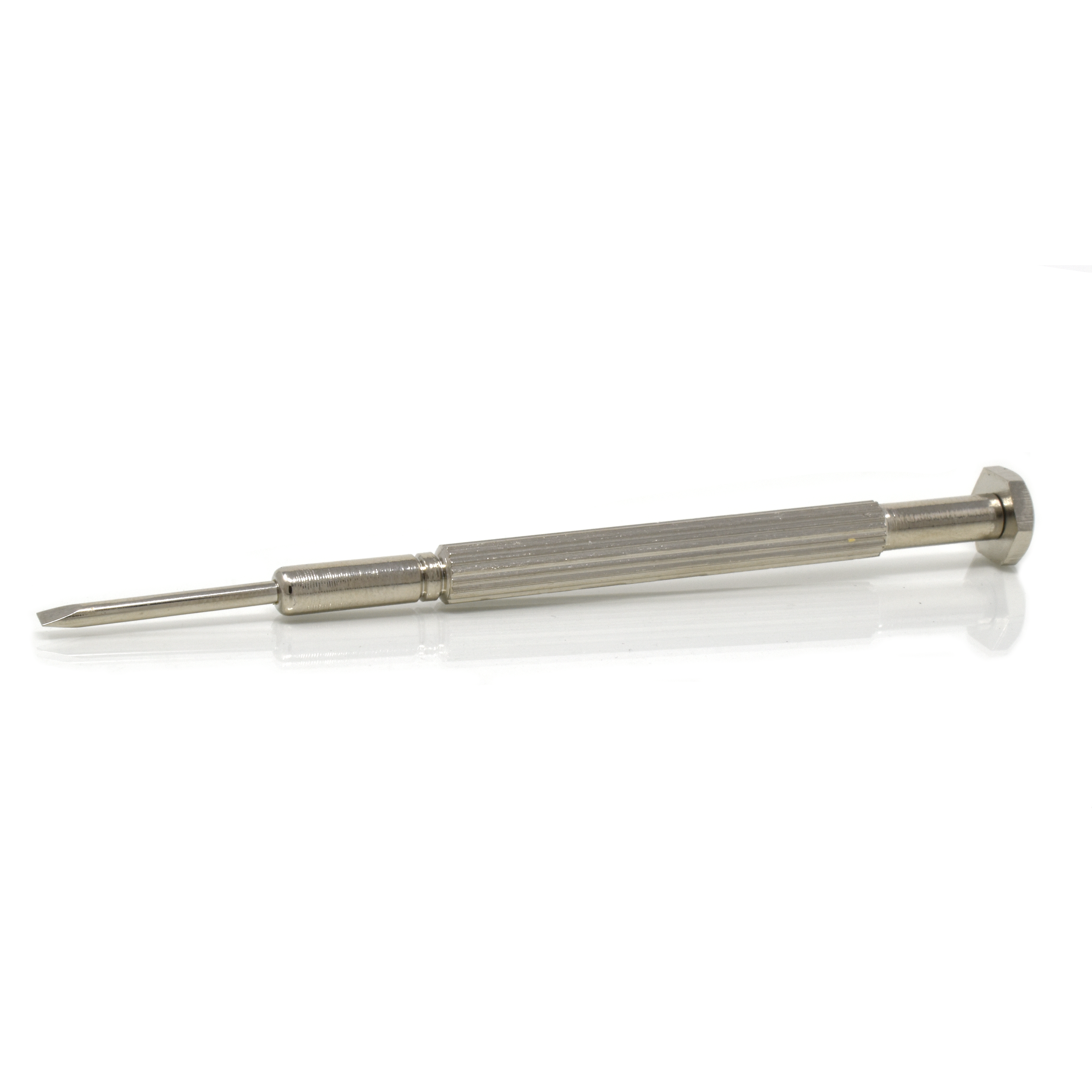
calibrating screwdriver

GTP-9459
carrying case for GTP-322 or GTP-323

GTP-892
battery, 9 volt, for meter

GTP-292
hose assembly, outlet, for GTP-191

GTP-835
fluorescing and calibrated standards set

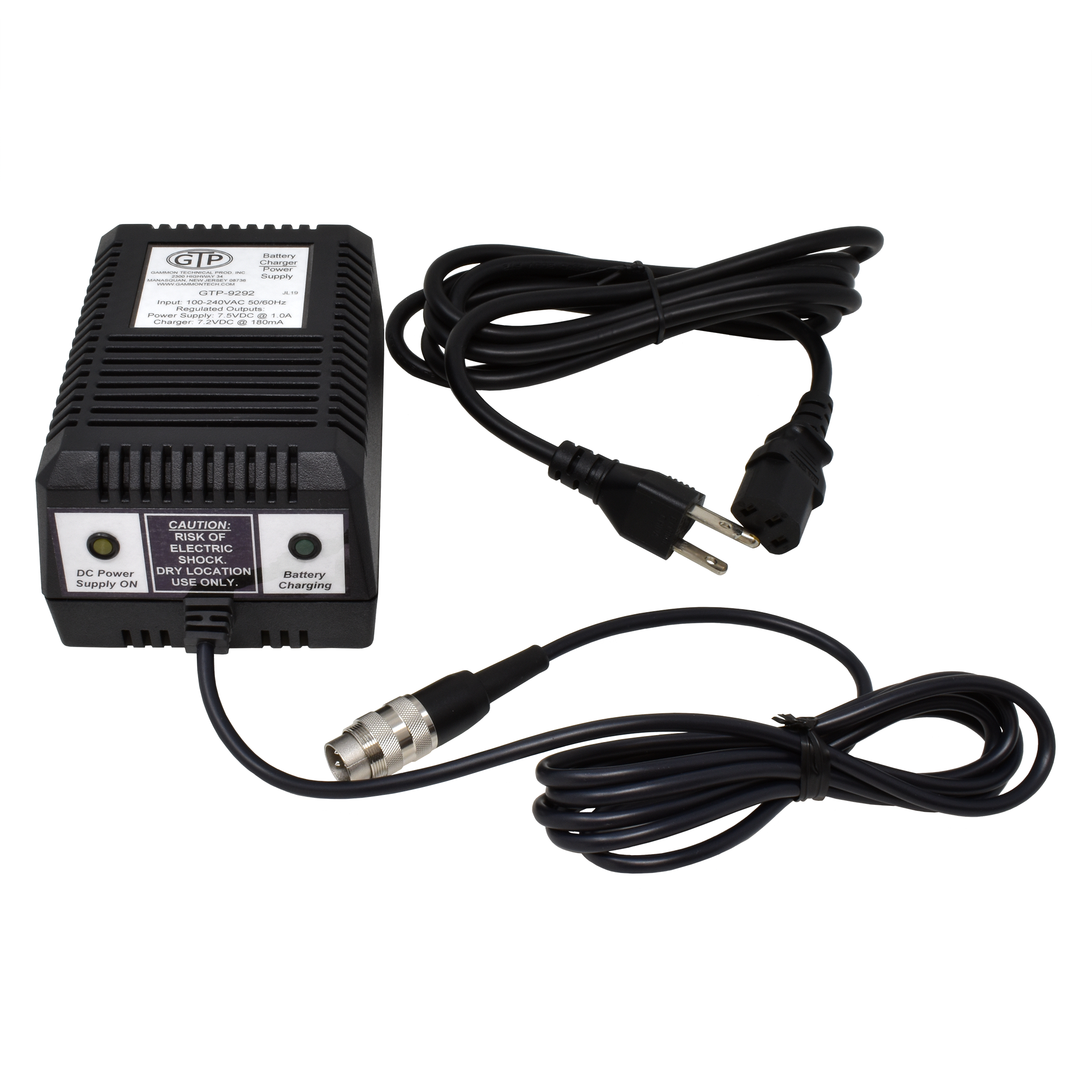
GTP-9292
power supply

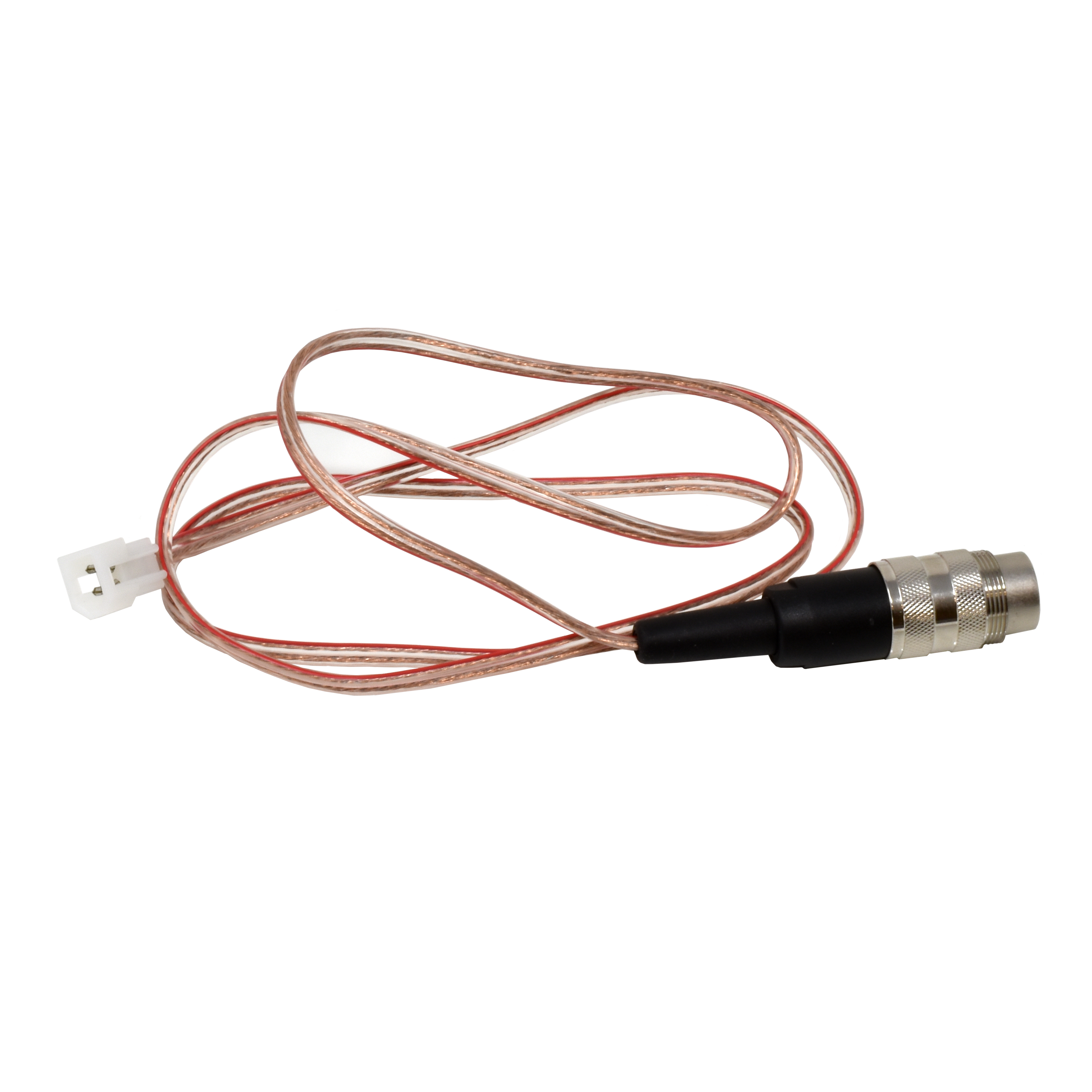
GTP-9329
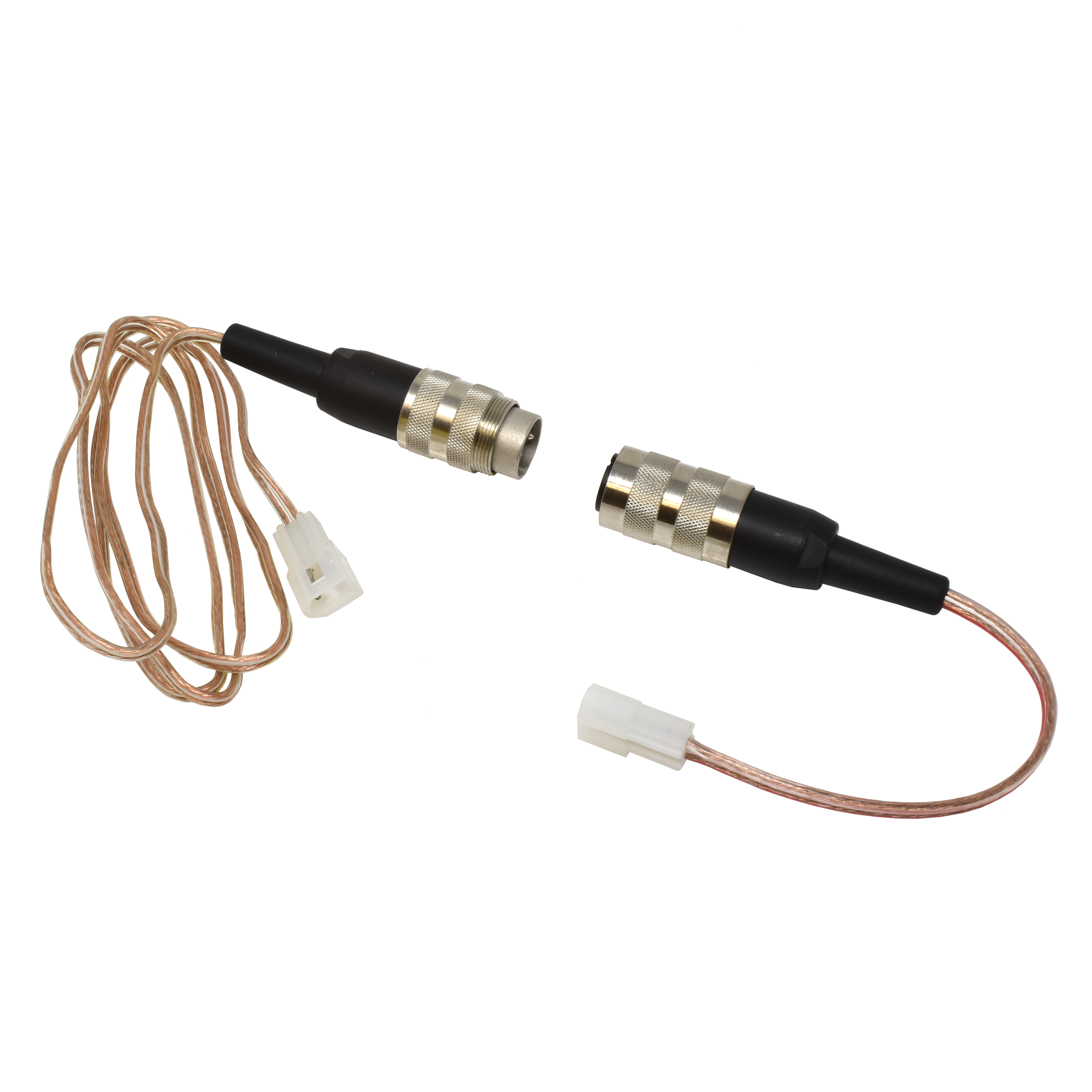
external battery power cable (optional)

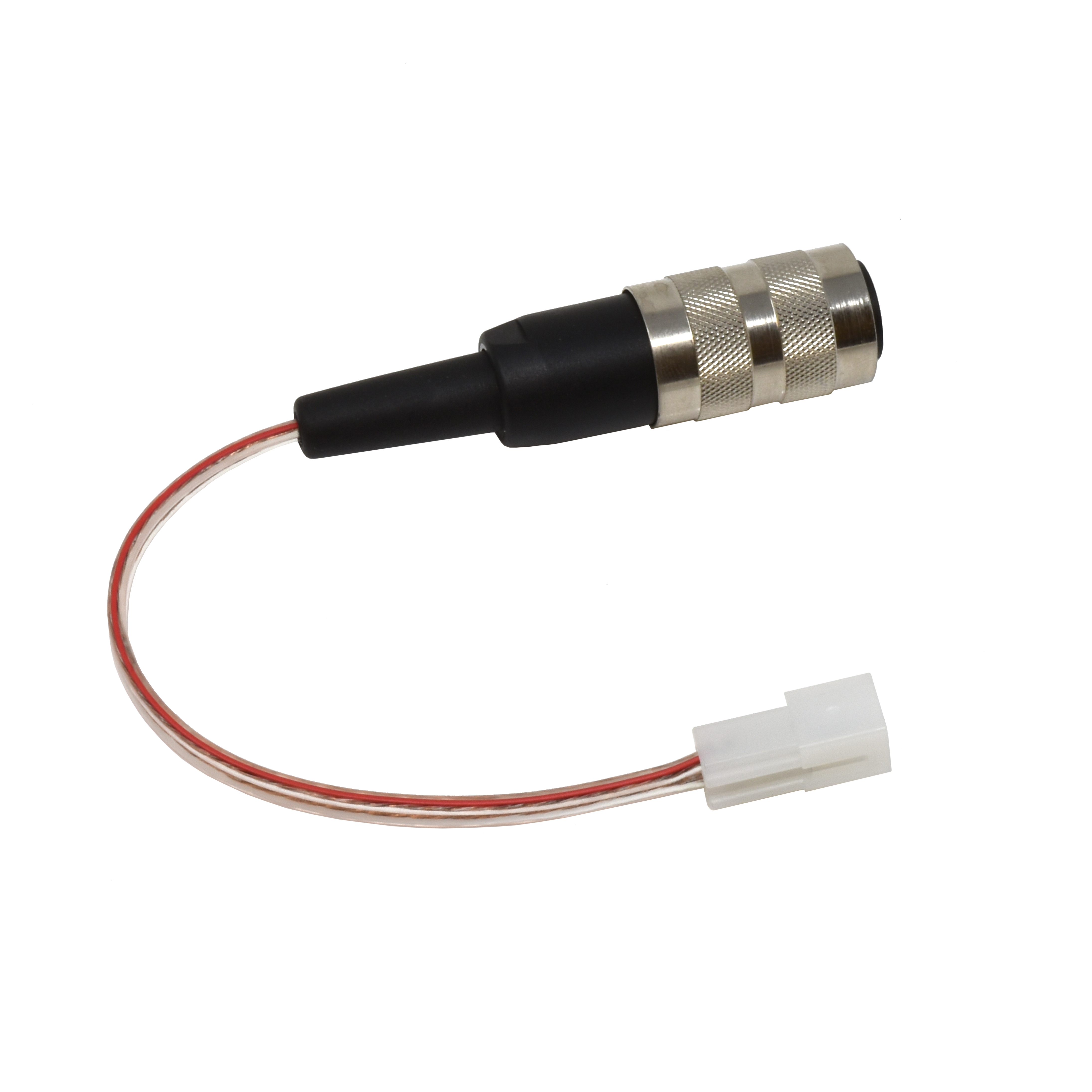
GTP-9331
external battery charging cable (optional)

GTP-9300-12
both external battery cables

GTP-240-5
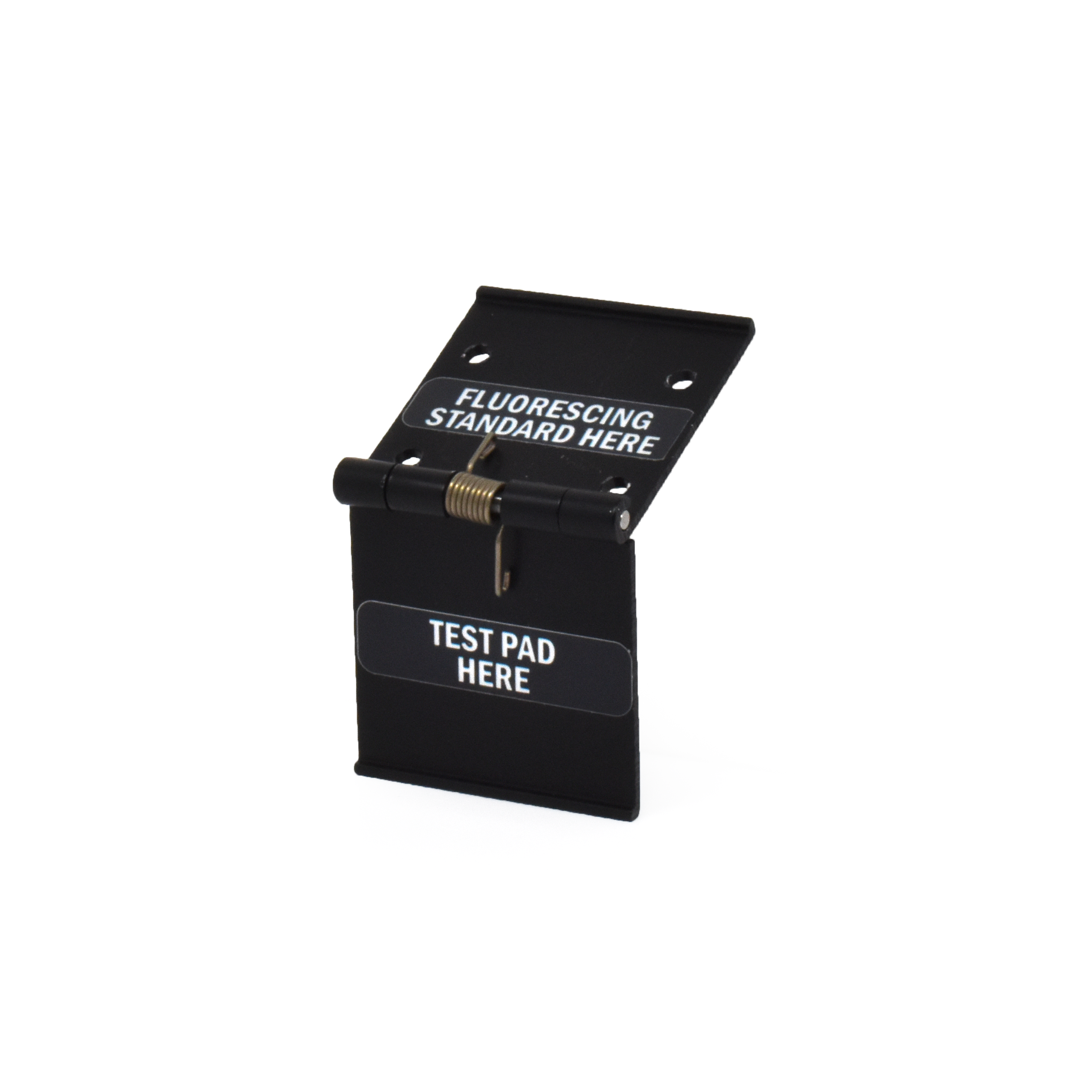
hinge

GTP-768
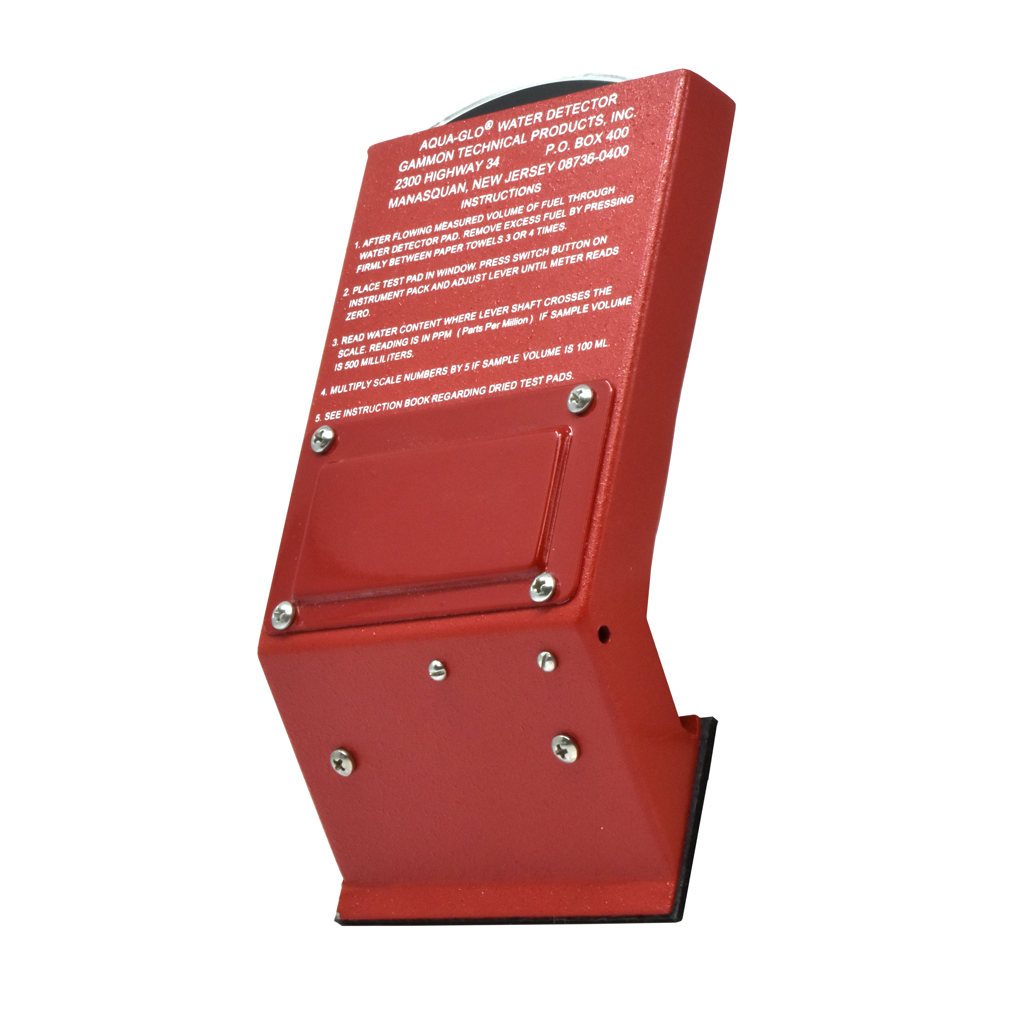
instrument pack

GTP-834-15
calibration tape

GTP-890
meter, analog

GTP-898
rubber foot

See Also:

GTP-1074-1
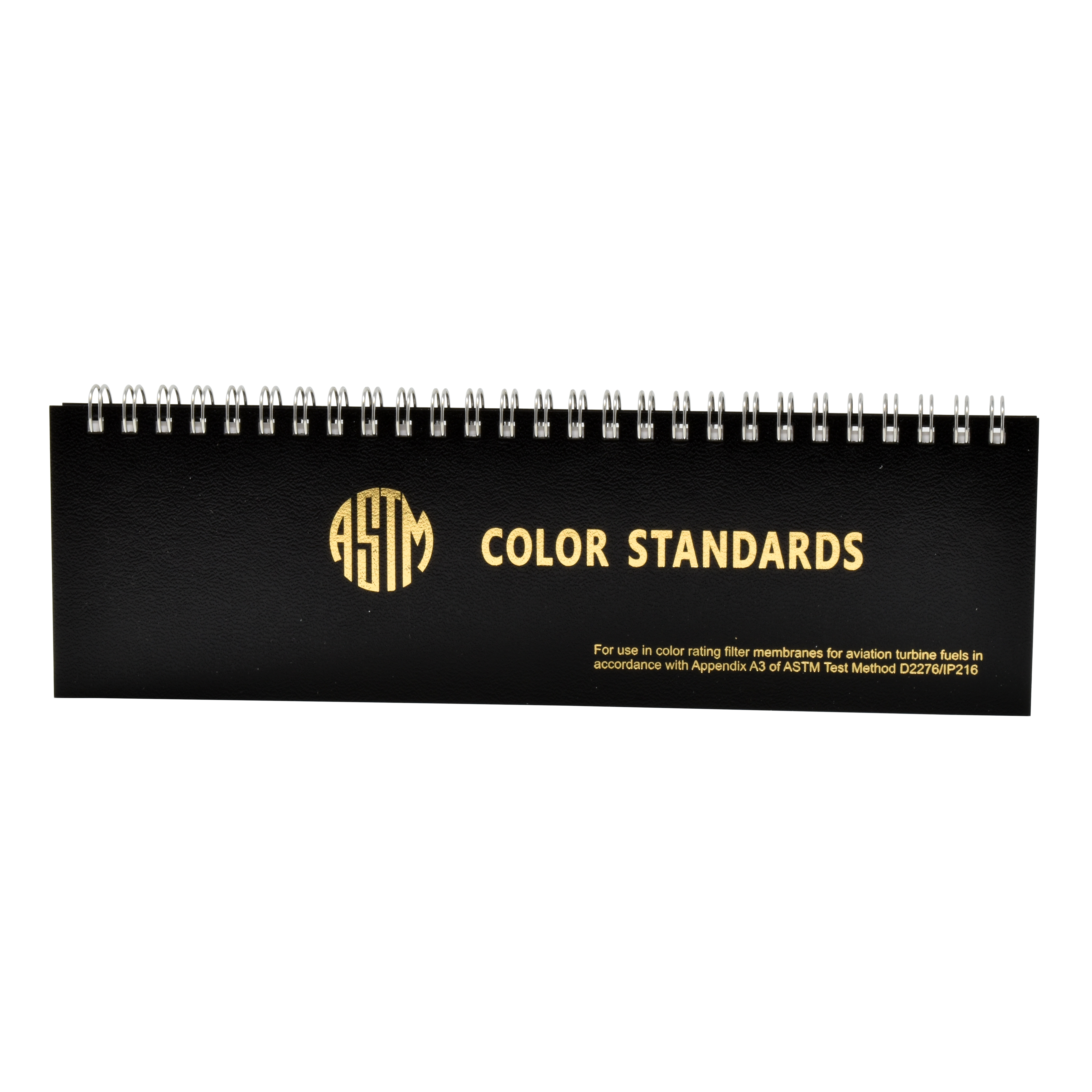
color rating book

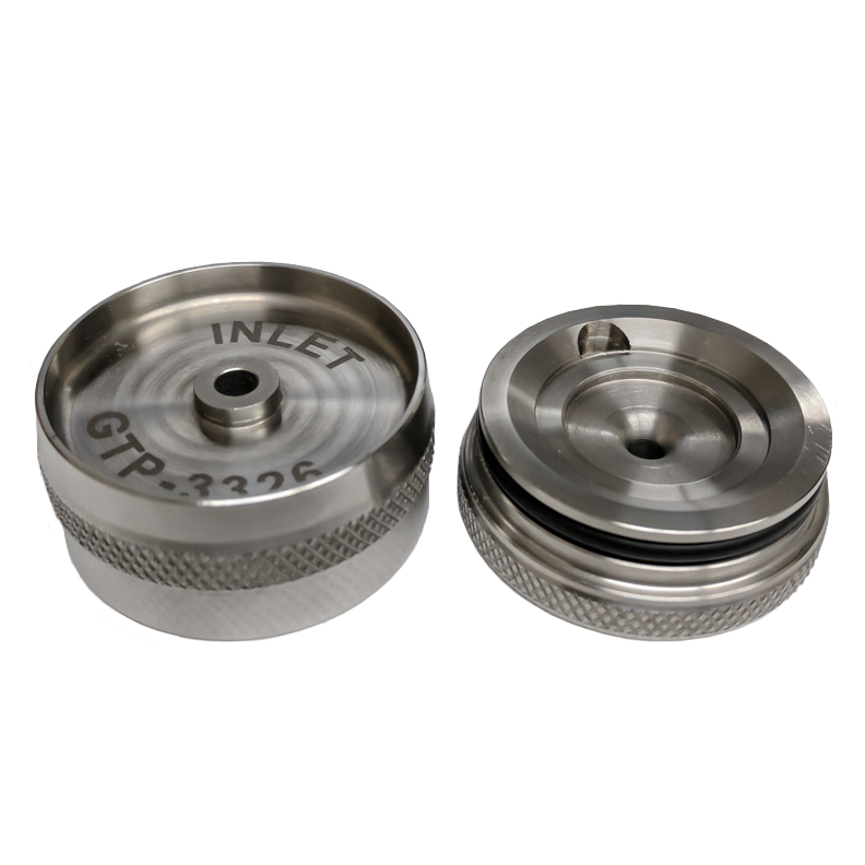
GTP-3326
stainless steel pad holder (25mm)

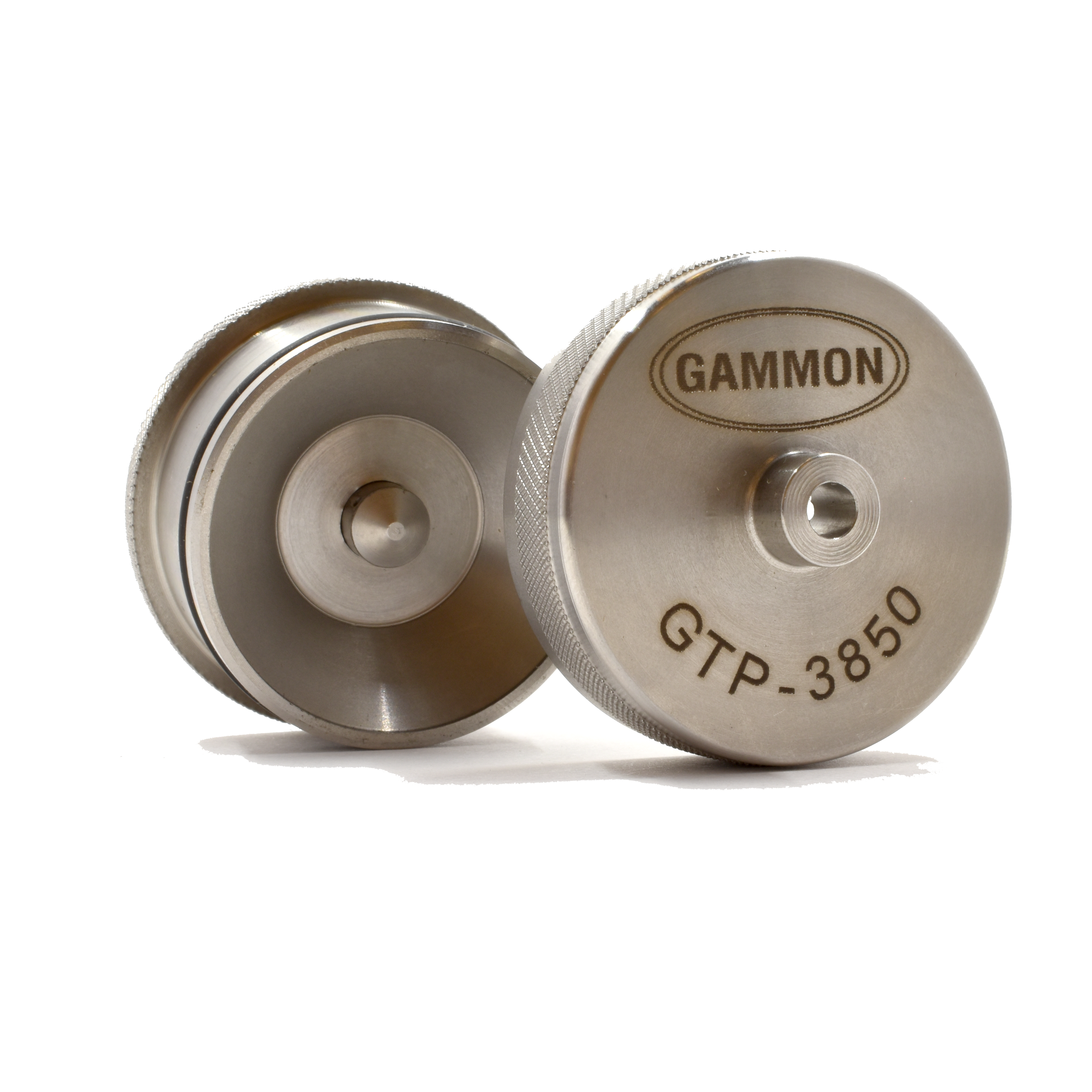
GTP-3850
stainless steel pad holder (37mm)

Bulletin 86: Aqua-Glo® Water Detector2024-10-08T20:28:08+00:00

Bulletin 85: Tank Sampling Device

New and Improved Tank Sampling Device

Take a sample from the bottom surface, or any level, of an underground tank, barge, or tanker cargo tank for inspection

The new version of this product has been designed so that the cover will fit a Mason jar as well as a bottle. The stopper will fit any drink bottle or common gallon jug.

Proper housekeeping of a tank farm requires that management knows the conditions of tank bottom accumulations. Is there a water bottom? What color – clear, brown, black? Is there any scum or obvious microorganism material?

The importance of knowing that the settled water in the sump of a storage tank is discolored cannot be overstated. After all, the coloration of the water is caused by contamination of the fuel itself. So when dark-colored water is found, it should be removed and the fuel should be checked using the color rating of filter membranes (ASTM D2276).

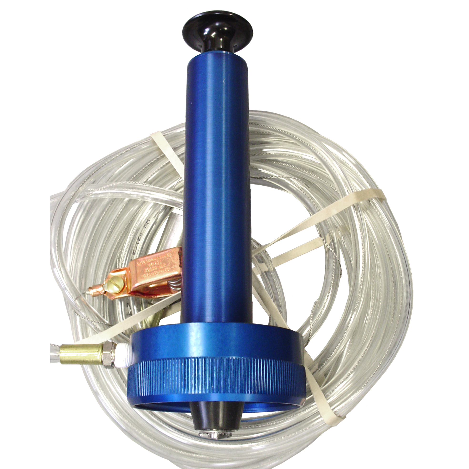
GTP-9670-20 (pictured above) combines a threaded cap that will fit a standard Mason jar (sold separately) with 20 feet of weighted, bonded polyurethane tubing. Simply lower the weighted end of the tubing to the desired level and operate the plunger pump to draw the sample. The assembly comes complete with internal bonding and grounding wire and clamp.

Every pump comes with both a jar connection and a conical stopper, designed to seal on the opening on a bottle or container with a 0.70-1.10” inside diameter.

How to Order

GTP-9670
pump with 10 or 20 feet of hose

GTP-2811
16oz glass jar

GTP-8649-2
replacement 20′ hose with fittings

Bulletin 85: Tank Sampling Device2024-10-08T19:00:29+00:00

Bulletin 84: Hydrant Pit Shut-Off Valve

Refueling Hydrant Pit Shut-Off Valves

Overview

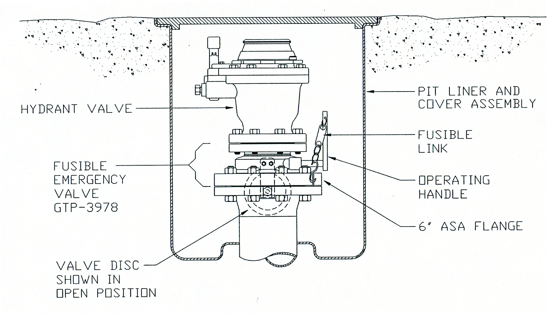
One thing is true of all hydrant pit control valves, and that is that they occasionally leak and/or need service. To stop the leak or service the valve without depressurizing the hydrant system, or a portion of it, a manual shut-off valve must be located between the hydrant pipe connection and the hydrant pit control valve.

Shut-off valves are sized either 4×4”, 6×4”, or 6×6” depending on the hydrant pipe size and the connection size of the hydrant pit control valve. The shut-off valve cannot be a “wafer” style valve; it must be flanged on the inlet and outlet. By using a flanged-type under-hydrant valve, the entire hydrant pit control valve can be removed, if necessary, and no leakage will occur.

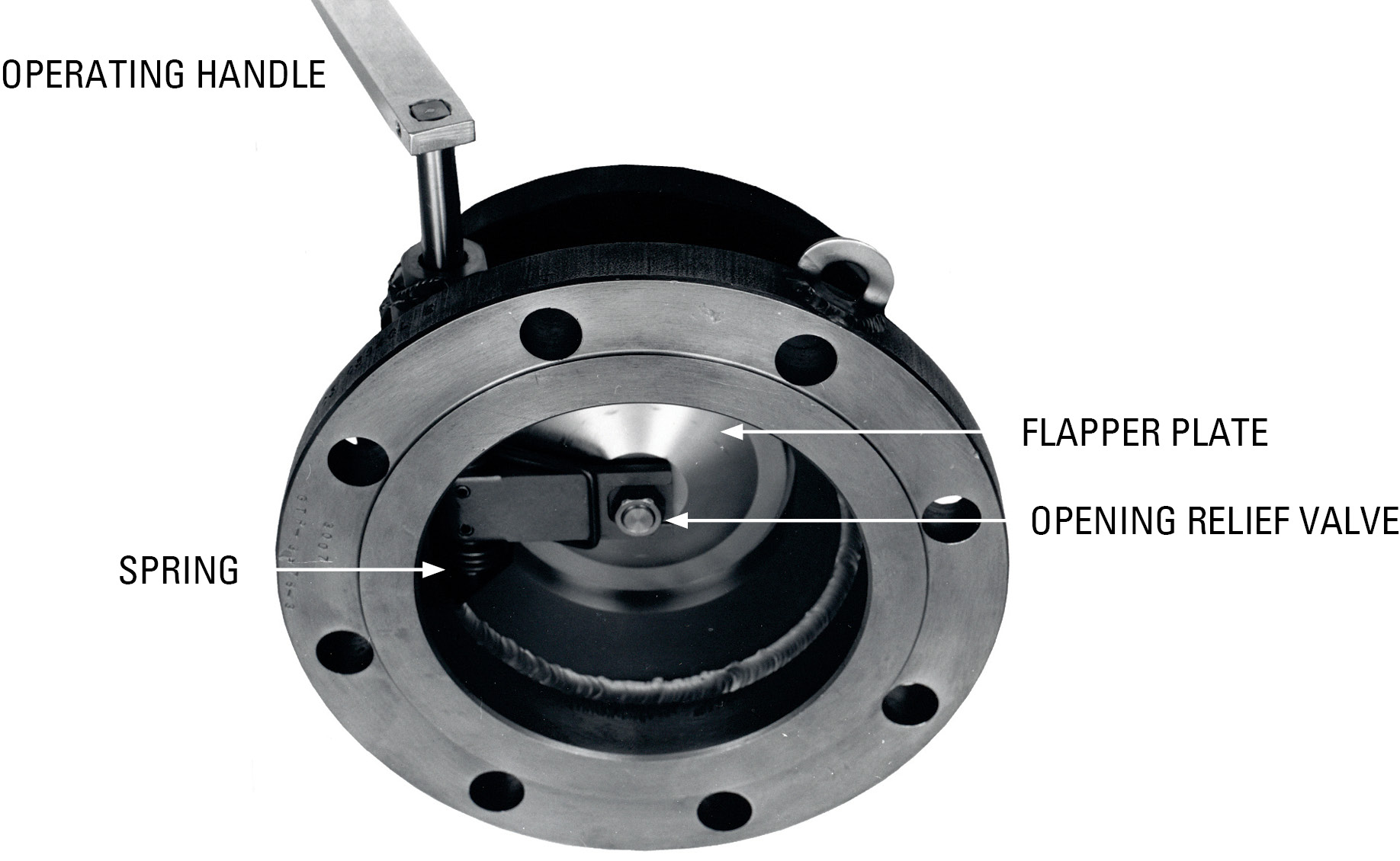
A shut-off valve may be a flapper-type or butterfly-type. The butterfly-type is good, but the disk remains in the flow path when the valve is open and acts as a restriction. The flapper-type is excellent on pressure drop, but a plain flapper cannot be opened against pressure. For this reason, our valve incorporates a “valve within a valve,” which automatically equalizes pressure when you start to move the operating handle. It is very easy to operate, yet provides all the advantages of a flapper-type valve. Other flapper-type designs rely on a separate tiny, vulnerable, manually operated valve for equalizing pressure. This is inconvenient, and it may also be accidentally left open.

The unique feature of the Gammon Under-Hydrant Shut-Off Valve is that, in addition to providing the standard shut-off feature, it can protect the airport and personnel from a disastrous fire because it closes automatically as soon as the temperature reaches 165°F (74°C). A fusible link in the chain that normally holds the valve open will melt at this temperature, resulting in instantaneous closure.

Under normal conditions, the valve can be closed easily by unhooking the chain. This action is totally independent of the fusible link. Unless the fusible link melts in a fire, it will never need to be replaced.

We usually refer to our Under-Hydrant Shut-Off Valve as an “Emergency Valve” because it will function in an emergency situation, which is usually more important to the approval authority than the basic shut-off feature. For any customer who does not need this added safety feature, we do not include the fusible link. Our valve then serves only as a “service valve,” like any other valve.

View of Device Looking Upward from Beneath the Valve

Design Features

This valve has special features that were necessary to make it pass the API-6FA fire test. This test requires that leakage through the valve or outside the valve will not exceed specified amounts after the seals have burned away at a temperature of 1600°F. To meet those specifications, we were unable to seal the operating shaft with o-rings so we used a unique labyrinth-type seal assembly that has proven to be reliable in other products we make.

Opening Relief Feature

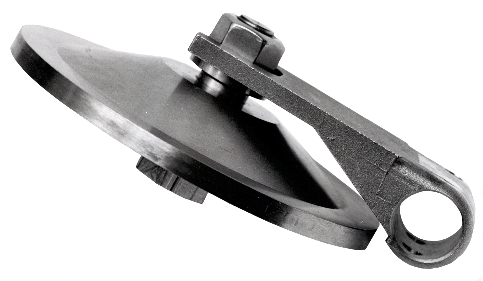
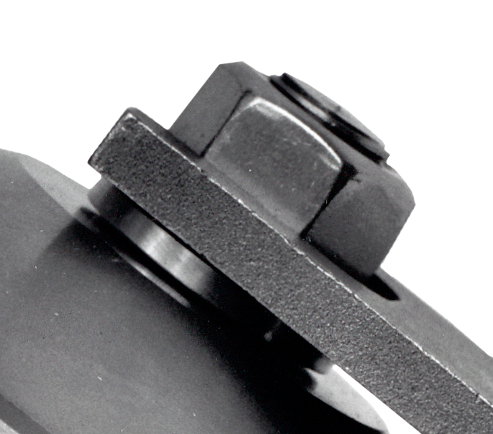
The primary advantage of this valve is its opening relief feature. Proven in many years of service on model GTP-2654, we made no changes when this feature was applied to model GTP-3978. In the closed position, the hydrant pressure assists the spring in keeping the valve tightly closed. Therefore, to open the valve, it is necessary to bleed fuel from the pressure side into the hydrant valve. To do this, the operator applies a small constant force (about 4-5 lbs.) to the handle. This force opens an internal bleed valve which passes fuel to the hydrant valve. When the pressure in the hydrant valve equals the hydrant system pressure, the operator can easily open the main valve and then attach the fusible link chain to arm it. A competitive valve on the market today has a separate, external bleed valve that can be opened by the operator who must reach under the hydrant valve to turn the handle. After the pressure equalizes, he must remember to close that valve.
OPENING RELIEF VALVE OPEN

Note cross-drilled holes for flow.

OPENING RELIEF VALVE CLOSED

General Information

Airport design engineers in many parts of the world are specifying the features of our Model GTP-3978-3 because they achieve two objectives that a plain butterfly valve (or even a fire-safe butterfly valve) does not offer. A non-fire-safe valve offers no leakage protection. A fire-safe butterfly valve is capable of stopping fuel flow in a fire only if it is in the closed position when a fire develops.

Clearly, an under-hydrant valve is expected to be in the open position except under unusual circumstances, such as for maintenance of the main hydrant control valve. Therefore, our valve is favored because it not only serves as a maintenance valve, but also will sense the presence of a fire and then close automatically to ensure that the fire will not be enhanced by more jet fuel.

Under such a condition, the fire may develop intense heat that will destroy all of the seals in any valve whether it is a butterfly or flapper-type. However, the unique design of our valve ensures that leakage will be minimized in accordance with API Bulletin 6FA even if the seals have been burned away.

In summary, our valves are in service at a number of airports worldwide, from New York’s JFK to Singapore’s Changi Airport. We have had virtually no replacement part orders, proving that these valves require no maintenance or replacement parts.

Our valves serve as manual shut-off valves and emergency valves. All working parts are solid stainless steel. They are very heavy duty. They offer almost no resistance to flow. Samples are available upon request. Once you have seen our valve and compared it with any and all alternatives, we are confident that you will agree no equal to our valve exists.

How to Order

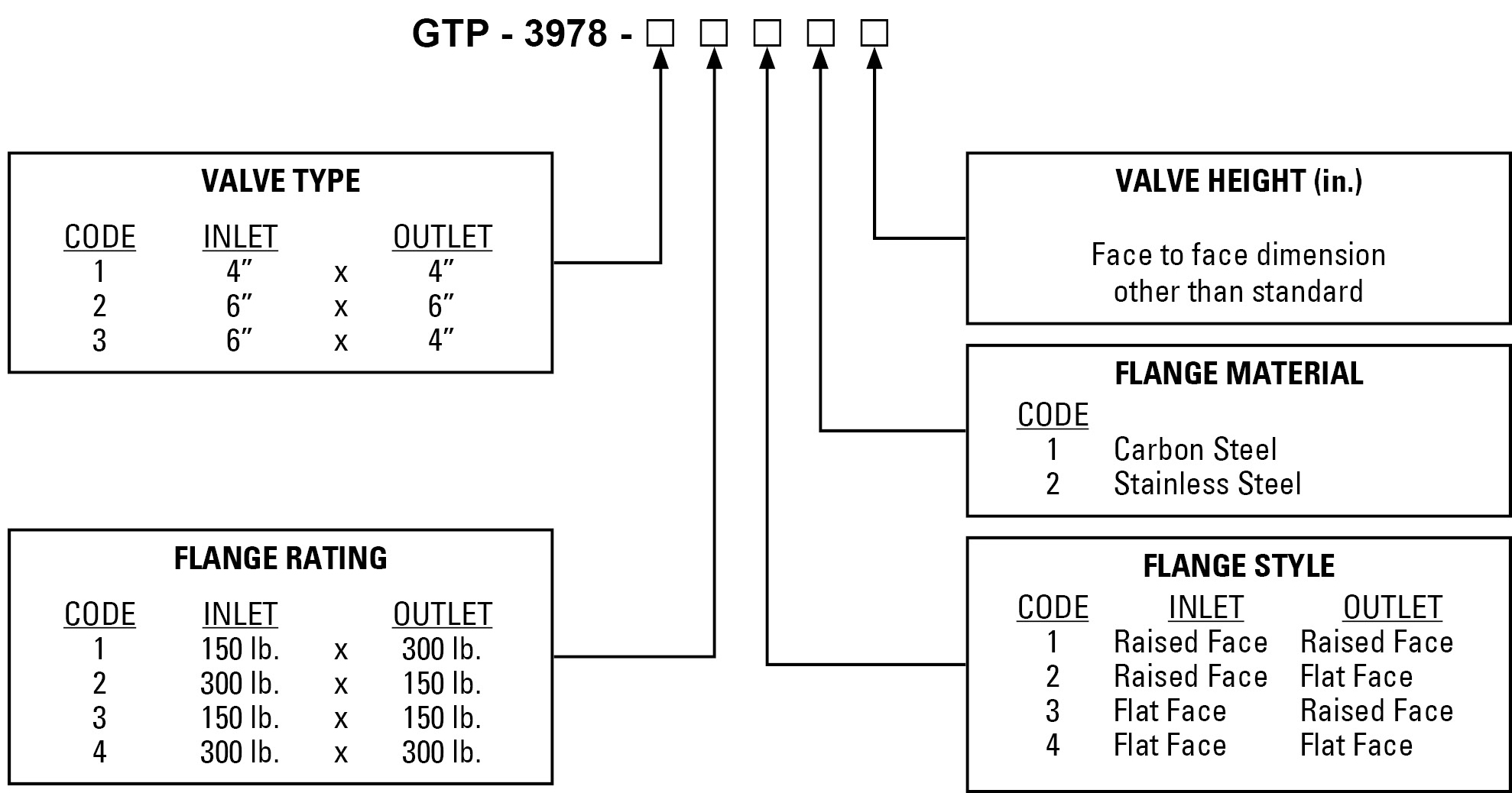
Approximate weights: 4” x 4” 150 lb. flanges 51 lbs., 6” x 6” 300 lb. flanges 78 lbs., 4” x 6” 150 lb. flanges 47 lbs.

EXAMPLE: GTP-3978-23126 is an emergency valve as follows: 6” x 6” valve type, 150 lb. x 150 lb. flange rating, raised face flanges, stainless steel, with a valve height of 6 inches.

Bulletin 84: Hydrant Pit Shut-Off Valve2024-10-08T18:47:36+00:00

Bulletin 80: ASTM Color Standards

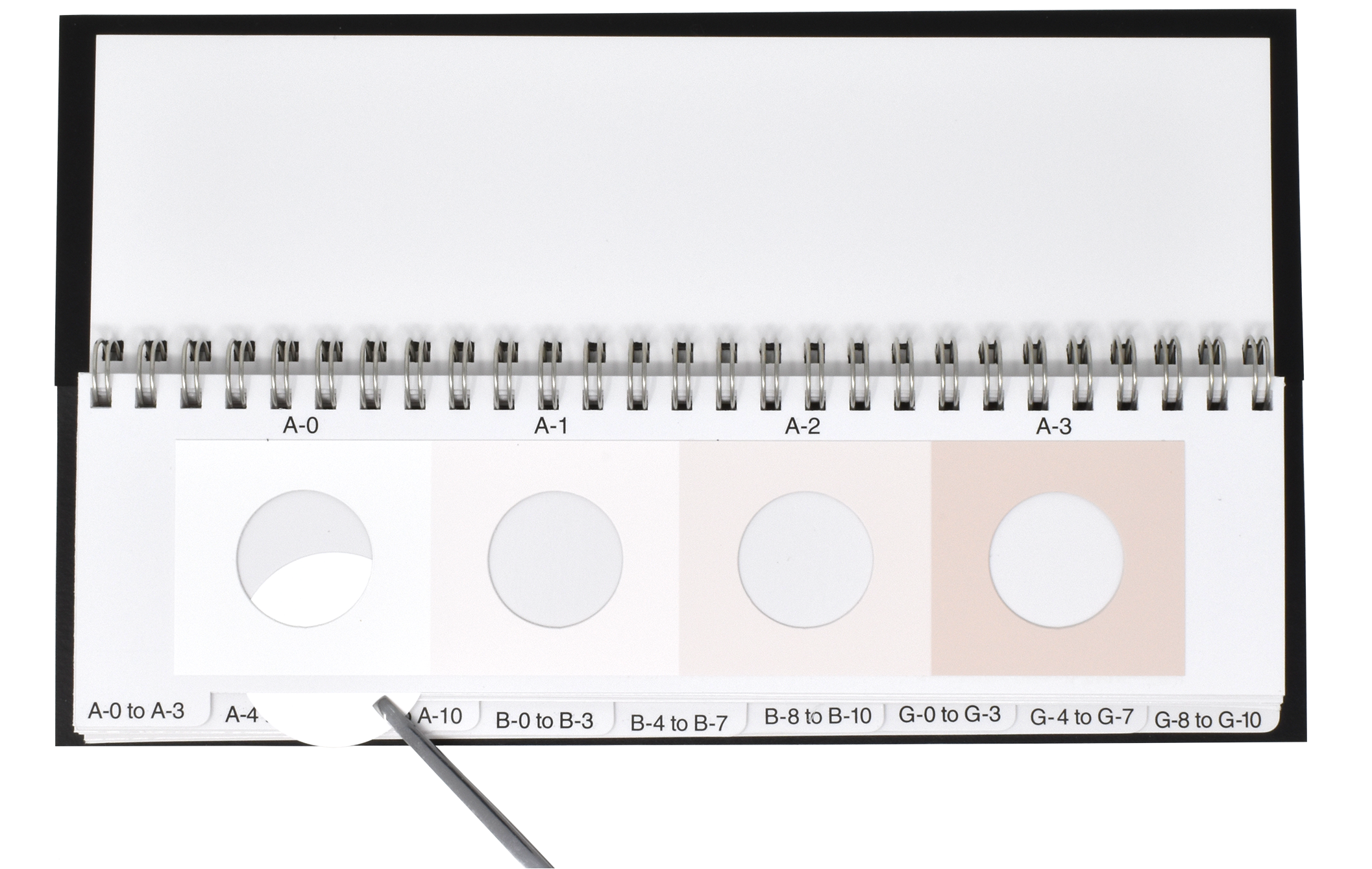
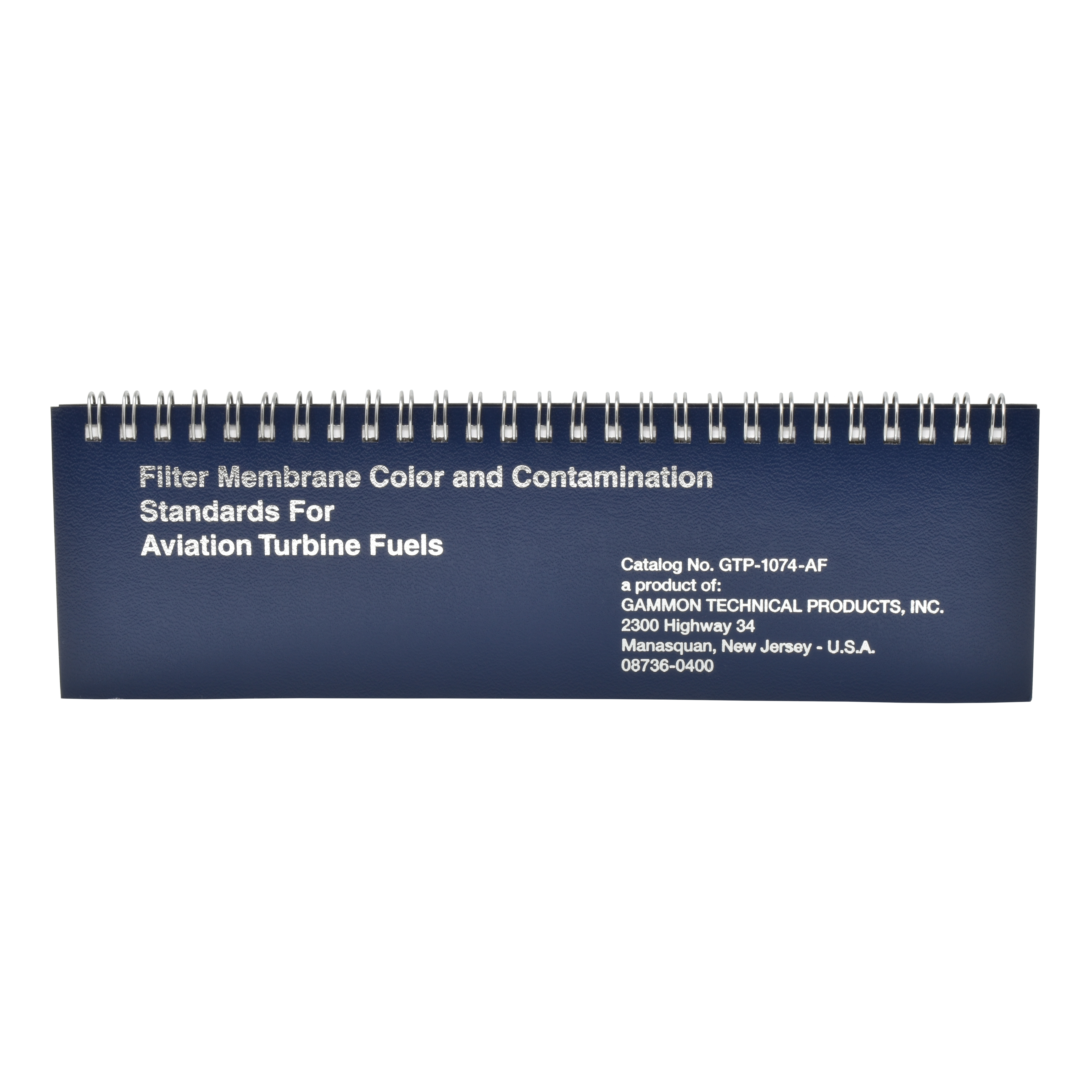
ASTM Color Rating Booklet

For use in color rating filter membranes for aviation turbine fuels
in accordance with Appendix X1 of ASTM Test Method D2276/IP216

Available through Gammon Technical Products distributors worldwide.

We are proud to have been appointed as the central custodian for this color standard booklet.

We supervise the manufacture and color certifications.

GTP-1074-1
standard color rating booklet

GTP-1074-AF
standard booklet, plus particle assessment guide

Specifications

Each color standard panel has been certified in accordance with the Munsell Color rating system to Triple A standards for chroma, value, and hue. The colors, as specified in ASTM D2276/IP216, are as follows:

Scale A

Rating
Number
Munsell CIELAB
L* a* b*
0 N 9.6 98.99 0.00 -0.01
1 2.5 YR 9.3/0.5 94.03 1.41 2.01
2 2.5 YR 9/1 91.08 2.69 3.79
3 2.5 YR 8.5/2 86.21 5.27 7.43
4 2.5 YR 8/3 81.35 8.90 12.37
5 2.5 YR 7/4 71.60 12.41 16.88
6 2.5 YR 6/3.4 61.70 11.07 14.37
7 2.5 YR 5/2.8 51.57 9.60 11.66
8 2.5 YR 4/2.2 41.22 8.50 9.60
9 2.5 YR 3/1.6 30.77 6.85 6.84
10 2.5 YR 2.5/1 25.61 4.48 3.83

Scale G

Rating
Number
Munsell CIELAB
L* a* b*
0 N 9.6/ 98.99 0.00 -0.01
1 N 9.3/ 94.03 0.00 -0.01
2 N 9/ 91.08 0.00 -0.01
3 N 8.5/ 86.21 0.00 -0.01
4 N 8/ 81.35 0.00 -0.01
5 N 7/ 71.60 0.00 -0.01
6 N 6/ 61.70 0.00 -0.01
7 N 5/ 51.57 0.00 0.00
8 N 4/ 41.22 0.00 0.00
9 N 3/ 30.77 0.00 0.00
10 N 2.5/ 25.61 0.00 0.00

Scale B

Rating
Number
Munsell CIELAB
L* a* b*
0 N 9.6/ 96.99 0.00 -0.01
1 5 Y 9.3/0.5 94.03 -0.60 4.21
2 3.4 Y 9/1 91.08 -0.70 8.05
3 1.7 Y 8.5/2 86.21 0.13 14.89
4 10 YR 8/3 81.35 2.78 19.60
5 10 YR 7/4 71.60 4.50 25.82
6 10 YR 6/3.4 61.70 4.28 21.57
7 10 YR 5/2.8 51.57 4.09 17.64
8 10 YR 4/2.2 41.22 3.60 14.46
9 10 YR 3/1.6 30.77 2.88 9.68
10 10 YR 2.5/1 25.61 1.96 5.76

Every color page is wire bound.

Each color standard has a 1 inch (25mm) window so that the membrane can be viewed for better accuracy in color rating.

Every color page has an index tab to speed up finding the right page.

Margins are provided at the ends of color pages to avoid fingerprints on color panels.

Fuel resistant lamination is provided on the back on each color page and on an interleaf between each color page. This prevents a wet membrane from soaking the page and possibly altering the color.

IMPORTANT NOTE: Instrumented tests have proven that some colors in the old, original booklets dated 1981 have changed over the years since they were originally manufactured. Those booklets have been declared invalid and must be destroyed.

ASTM D2276, paragraph X1.5.1.1 states the following:

Charts in use should be checked periodically against a reference set of color standards to eliminate the possibility that sunlight or soiling due to handling may have appreciably changed the colors. The reference set is a set of color standards obtained new, stored in dry, dark conditions, and is only used for the purpose of checking the standards in day-to-day use.

Bulletin 80: ASTM Color Standards2024-11-06T16:44:33+00:00
Go to Top