About Sandra Gammon

This author has not yet filled in any details.
So far Sandra Gammon has created 139 blog entries.

Bulletin 70: Air System Accessories

Tamper-Proof Air Pressure Regulator
GTP-1121

With the “key” removed from the knob, it is impossible to tamper with the air pressure adjustment. This unique feature makes this regulator superbly suited for use on airport refuelers for adjusting air reference pressures. An internal relief valve makes it self-relieving to prevent “creep” of the outlet pressure. Will control pressure with great accuracy between 10 and 200 psi. Price includes side-mounting hardware. Shown here with panel mount and optional key.

  • Connections are 1/2” FNPT
  • Maximum inlet pressure is 300 psig
  • Outlet pressure adjustable to 125 psig
  • Zinc body
  • Nitrile seals
  • Panel or side mount
  • Aluminum or plastic knob

GTP-1121
tamper-proof air pressure regulator

GTP-1121-1
key for air pressure regulator

GTP-2954C
pressure gauge, 0-160psi

Air Filter with Automatic Water Drain
GTP-1923

Designed to remove dirt and water from truck air systems, this filter will automatically drain collected water. The polyethylene filter element is rated at 5 microns. Steel shatter guard and manual drain cock included.

  • Connections are 1/4” FNPT
  • Maximum inlet pressure is 150 psi
  • Minimum inlet pressure is 15 psi
  • Polycarbonate plastic bowl
  • Internal automatic drain

Bulletin 70: Air System Accessories2024-12-30T17:26:58+00:00

Bulletin 67: Deadman and Water Control

Mini-Deadman™

The heart of any deadman is the switch. The switch in this deadman has a built-in rolling diaphragm seal, aluminum body (not glass, rubber, or plastic), and an 8 amp contact rating. It is hermetically sealed, yet is easily replaceable, incorporating “push on” type electrical connections, eliminating troubles with wire nuts or soldering. In addition, the housing is o-ring sealed and has an anodized aluminum switch carrier and cable base fitting. The strain relief is a spiral type with a watertight seal.

  • Made in USA
  • Material: urethane
  • Dimensions: 4” x 1¾”
  • Weight: 6 oz.
  • Durable
  • Compact
  • Inexpensive
  • Easy to repair
  • Wear resistant
  • Stainless steel trigger
  • Good from -55° to 180°F
  • Low operating force required
  • Easy to assemble/disassemble
  • Can be hung on trigger for storage
  • Designed for the aviation environment
  • Compatible with any deadman system
  • Body screws are recessed to prevent damage

NOTE: These handles are not suitable for AC applications unless and intrinsically safe barrier/relay is used.

Mini Deadman Handle
electric, pneumatic, or hydraulic

Mini Deadman Handle with Cord
straight (up to 500 ft.) or coiled (25 or 50 ft.)

GTP-8393-1
Mini Deadman trigger assembly

GTP-8394
Mini Deadman shoulder screw

GTP-8397
Mini Deadman housing

Dura-Deadman
GTP-9720

Solid, super durable, cold molded, and virtually unbreakable, this handle is made of pure polyurethane. This new Dura-Deadman handle is the strongest and most reliable deadman we offer. It was tested for over half a million cycles, we’ve driven over it with trucks, and it’s been dragged on pavement – all without failure. It features replaceable polyurethane drag bosses for even longer life. Made in USA.

Electric

These handles are weather-tight sealed. They are not suitable for AC applications unless an intrinsically safe barrier/relay is used.

Switch data: Normally open switches are standard. Add “-NC” to the part number for normally closed.

Pneumatic/Hydraulic

These handles each contain two valves to provide fast reaction time. Seals are Buna/Nitrile.

Gammon One-CC Water Probe

Meets EI-1596

Detects water in filter separator sumps

Allows periodic testing requiring only 1cc of water, even during refueling

Thousands in service worldwide

The problem with water detector probes has always been that others are impossible to test periodically without stopping flow, dismantling, or injecting water into the vessel. People are afraid that too much water may be injected. The One-CC Probe solves this simply. First, it has a patented design that only needs 1 ml (1cc) of water for a complete test. Second, it has a built-in water pump, and this pump is only capable of injecting 1 ml (1 cc) of water.

The One-CC™ Water Detector Probe is designed for use in any intrinsically safe electronic control system sensitive enough to detect water by conductivity/resistance. This new probe can therefore replace existing probes in Meggitt/Whittaker equipment if they utilize our replacement controls.

We offer electronic controls in DC, AC, weather tight and explosion proof versions.

Basic Water Probe
GTP-9734

lower price – includes circuit tester

For those who prefer a smaller and less expensive water probe. All-stainless construction. Push button circuit tester. Can be fitted to a simple valved drain line assembly which allows for true water testing to EI1596. 3/4” NPT or BSPT connections.

Deadman Hose
GTP-1202

both hoses have neoprene construction, Buna-N tubes

Manufactured to Gammon Technical Products, Inc. specifications, this hose is superior to any available air Deadman hose on the market. It is suitable for all refueling operations.

The tubes are made out of Buna-N (nitrile rubber) to resist fuel from cross-leakage in the control system. The braided, reinforced tubes have neoprene covers to resist oils that contaminate ramp areas. A special additive is included to give the cover superior resistance to cracking.

Available in cut lengths or reels, with or without fittings.

Inside diameter 1/4 inch
Operating pressure rating 200psi
Burst pressure rating more than 800psi

NOTE: all standard 1/4” twin welding hose has neoprene tube, which will fail when fuel gets in the air system. This hose has Buna N nitrile rubber tubes.

Deadman and Water Control Systems

GTP-1750
combination deadman and intrinsically safe water control system

GTP-1750-5
water control system

GTP-1750-1
deadman system 120VAC with Dura-Deadman handle

For full range of options, please contact Gammon Technical Products or your distributor to place a custom order.

Bulletin 67: Deadman and Water Control2024-12-30T17:27:25+00:00

Bulletin 65: Meter Monitor

Closed Circuit Testing with the Meter Monitor

No need for a measuring bucket. No need to dispose of fuel.

When performing filter membrane tests, the difficult part of the task is disposing of the test fuel. The Meter Monitor solves that problem completely. The flush and the test fuel are both returned to the fuel system and are never exposed to air, rain, or other contaminant sources. No buckets, funnels, or fuel spills. The Meter Monitor has two 1/8” NPT connections (connections are 1/4” NPT, inlet and outlet; we install bushings to 1/8” NPT).

Available with gallon or liter calibration.

NOTE: The standard model is made for petroleum service (jet fuel). An optional version for metering anti-icing additive (diEGME) is also available with specially-designed seals.

Testing Procedure

NOTE: The return line may also be connected anywhere that the pressure is reasonably less than the sampling pressure – to the storage tank, the truck tank, even a venturi throat. For operating at pressures over 125 psi, contact the factory or your distributor.

  1. Install a return connector at the inlet of the system pump (GTP-992-4MS).
  2. Using a MiniMonitor® housing that you may already own, insert a plastic monitor (see Bulletin 8).
  3. Install the Meter Monitor between the MiniMonitor® assembly and grounding hose (GTP-1110) which comes with the MiniMonitor® kit.
  4. Turn the MiniMonitor® valve to the stop position.
  5. Start flow in fuel system and read the meter position, for example 000089.23
  6. Connect the MiniMonitor® inlet to the sampling connector and connect the outlet of the hose to the return connector.
  • NOTE: The six numerals to the left of the decimal point read whole gallons. The right hand window reads tenths (0.1) of gallons. The dial reads hundredths (0.01) and can be estimated to 0.002. This is a non-reset type meter.
  1. Turn the MiniMonitor® valve to the flush position. If you plan to flush one gallon, stop the flushing after one gallon. In this example, stop at a reading of 000090.23.
  2. Turn the MiniMonitor® valve to the test position. Then turn the valve off when the correct number of test gallons has passed. Disconnect the return connection, then the sample connection.

No muss.

No fuss.

No mess.

The test is finished.

How to Order

GTP-1850
Meter monitor,
US gallon calibration

GTP-1850A-1
Meter monitor,
US gallon calibration with special seals for FSII, DiEGME, etc.

GTP-1850A-3
Meter monitor,
Metric (liter) calibration

GTP-1850A-4
Meter monitor,
Metric (liter) calibration with special seals for FSII, DiEGME, etc.

Bulletin 65: Meter Monitor2024-12-30T17:26:04+00:00

Bulletin 63: Water Sump Float Tester

Water Sump Float Testers

for testing the emergency shut-down system on aircraft refueling systems

GTP-1787

Water Sump Float Tester, Basic Model

A controlled volume of water is slowly pumped by hand into the filter separator sump. If the emergency shut-down system is operating correctly, fuel flow will stop automatically when the level of water in the sump reaches the sensors. This test is performed while the fuel system is operating.

When the test has been completed, and while there is still pressure in the fuel system, the operator opens a drain valve that directs the liquid from the filter separator sump to the bucket (Model GTP-1787) or to the transparent measuring container (Model GTP-1799). Any fuel that is drained will float on the water. The operator can then confirm that all of the water that was injected into the sump has been removed.

Model GTP-1799

Tester with 2-wheeled Cart

A transparent measuring container at the top has an adjustable level indicator so that the operator can see that all of the water that was pumped into the filter separator sump has been recovered. The water filling port is at the top – see the chained plug. An overflow pipe carries excess fuel to a 5-gallon slop collector on the lower platform. See the drain valve for emptying slop collector.

Constructed with materials that will not rust or corrode in water, this specially-designed apparatus can be stored for long periods with clean water inside without danger of malfunction. Stainless steel and brass are the primary materials. The hoses are pressure rated for 250 psi, five times higher than is expected in a fueling system. Buna-N is used in the hose tube while Hypalon® is the cover material.

General Discussion

Testing of water sump controls has been a controversial subject for many years (refer to GamGram Number 1). Some operators are afraid to pump water into the sump to test the system because they fear “human failure,” resulting in water getting into an aircraft. However, if these systems do not perform correctly, the filter separator cannot do its job of preventing water from getting into the aircraft. In a typical 600 gpm filter separator, the separator elements will be underwater if 5 gallons are collected – any additional water goes into the aircraft.

Some operators rely on the procedure of checking the sump drain for the presence of water after each refueling operation. This is surely a good practice but it is subject to “human error.” Other operators use float testers to check the operation of the control circuit. This good practice checks everything except the float. Periodically, the float must be tested to ensure that it will float on a fuel/water interface.

From the above comments, the conclusion is that periodic injection of water to test the entire system offers the greatest reliability.

Testing Procedure

  1. Place a measured volume of clean water in a bucket or graduated container. Mark the level of water on the container. See note under Step 4, below.
  2. Attach the swivel coupler to the water drain outlet of the filter separator.
  3. Start fuel flow through the system. A refueller truck can be recirculated. A hydrant cart must dispense to tankage.
  4. When normal flow rate and pressure have been established. open the water drain valve and pump water into the filter separator sump.‌
  • NOTE: The volume of water required to activate the float or sensor in the filter separator depends on the design of the sump. The volume must be determined by a test for each piece of equipment. To insure against contaminating the flow system, the operator must not inject more than this amount of water.‌
  • If the emergency shut-down system operates properly, fuel flow will stop automatically. If it does not stop fuel flow, the system must be repaired before the aircraft can be refueled.‌
  1. To remove water from the sump after the test, open the small toggle valve with the return hose in the water container. Allow some fuel to flow into the container to be sure that all of the injected water has been returned. Close the toggle valve. When the water has settled to the bottom of the container, the water level should be at the original mark as created in Step 1.
  2. Close the water drain valve and remove the swivel coupling.

Bulletin 63: Water Sump Float Tester2024-12-30T17:25:43+00:00

Bulletin 62: Heaters for Sumps and Drains

Heaters for Filter Separators

Rated “Explosion Proof” – NEMA 7 Class 1, Groups B/C/D, Division 1

Features:

  • Stainless steel sheathing will not rust

  • Adjustable thermostats 40-120°F

  • 240 volts, 50/60 Hz, single phase (most are also available in 120 VAC)

  • Watt density: 20 watts/in²

  • 150 psi working pressure
  • Conduit connections 1″ NPT
  • Designed for use on gasoline, kerosene, jet fuel, diesel or No. 2 fuel oil

  • Made in USA
Watt Rating Probe Length (in.) Thread NPT (in.) Model No. (standard) Model No. (with light)
300 6.0 1 ¼ GTP-1756 GTP-1756L
750 7.0 1 ¼ GTP-1757 GTP-1757L
1000 9.7 1 ¼ GTP-1758 GTP-1758L
1500 12.5 1 ¼ GTP-1759 GTP-1759L
300 12.5 1 GTP-1760 GTP-1760L
750 18.5 1 GTP-1761 GTP-1761L
1000 24.7 1 GTP-1762 GTP-1762L
1500 38.5 1 GTP-1763 GTP-1763L

Shown below is the typical pipe and fitting arrangement for a 300 watt heater installation in a drain system. The nipple at the upper left screws into the sump drain valve at the bottom. The optional indicator light is in the foreground. The electrical conduit enters on the opposite side of heater.

General Discussion

Our heaters are made specially for us by a highly qualified manufacturer with many years of experience. The purpose of a heater in a filter separator is to prevent the formation of ice in the water drain system. This makes it possible to drain water that has collected. Attempts have been made in the past to heat the entire filter separator by applying insulation but this has been found to be impractical because there are too many ways that heat can be lost. Furthermore, when insulation has been soaked in rain water, which is nearly impossible to prevent, heat loss is increased and severe corrosion develops.

The usual approach is to have one heater for the sump and a second one for the drain piping. The sump heater should be carefully located so that it is as close as possible to the surface on which water collects. However, it should also cross over the drain port and under the float if a float operated pilot valve is used. If the vessel is exceptionally large, a second sump heater may be installed in the drain piping only.

Most of the heaters covered in this bulletin are used as replacements for heaters that have failed. If you intend to install a heater in a filter separator that was not designed with a proper fitting, be advised that the welding must be done by an ASME qualified shop if the vessel was originally built to Section VII of the ASME code.

The most common failure of a heater is rusting of the steel sheaths. The frequent result of such a failure is that fuel will leak into the electrical housing and it sometimes will fill up the electrical conduit that carries power to the heater. When replacing a heater under such circumstances, we recommend that the conduit be thoroughly dried and new wires installed. The reason for this is that ignition could occur from the arcing of the thermostat. Although a fire in the conduit is “safe,” shorting could occur because of burned insulation.

Notes

  • 1

    When installing one of our heaters, the thermostat must be adjusted. Remove the cover and note a black dial knob that is calibrated from 40-120°F. Turn this knob until the preferred temperature is set next to the indicating button.

  • 2

    There are two screws that hold the thermostat. The set point marker is the screw that 60°F can be turned to.

  • 3

    You can easily check the thermostat for accuracy at any time if you know the temperature of the contents of the filter. Turn off the power first. Then turn the knob slowly from a higher setting. You will note an audible “click” when you read the temperature that causes the thermostat to engage the circuit. If you now turn the knob in the other direction, there will be another “click” when the thermostat disengages. The temperature spread is about 5°F.

Bulletin 62: Heaters for Sumps and Drains2025-01-16T19:32:49+00:00

Bulletin 61: Hydrometers, Thermometers, & Accessories

NOTE: For customers who prefer non-mercury thermohydrometers, add a suffix “B” to the part number for any of our API Gravity or Metric Density instruments listed below. Safe and easy, non-hazardous clean-up in case of breakage.

API Gravity Hydrometers and Thermometers

GTP-915GB is shown. Other models may vary in appearance.

API Gravity Range Thermometer Range Divisions Length (mm) ASTM No. GTP No.
29-41 0-150° F 380 S554HL GTP-1680GB
37-49 0-150° F 405 S561HL GTP-9155GB
39-51 no thermometer 335 5H GTP-1676
39-51 0-150° F 330 S555HL GTP-915GB
49-61 0-150° F 380 S556HL GTP-1681G
59-71 0-150° F 380 S557HL GTP-1682GB
64-76 0-150° F 405 S568HL GTP-9185GB
69-81 0-150° F 380 S558HL GTP-1683GB

Metric Density

The symbols on the left side of the charts below may help you to select the hydrometers you should order. Hydrometers and thermohydrometers marked with these symbols have special ranges that avoid the need to purchase two instruments to cover the range for aviation fuels. ASTM has assigned special numbers and has officially approved them. For example, most jet fuels have an API gravity range that requires ASTM S555HL but there are some fuels that need ASTM S554HL to reach 37° API. So the new ASTM S561HL, with a range of 37-49°, covers all jet fuels. ASTM S562HL covers Avgas. Each symbol also indicates additional qualities as described below:

For metric density, ASTM 321H covers the range from 775 to 825 kg/m³, avoiding the need to purchase two hydrometers, ASTM 314H & 315H. Likewise, for a thermohydrometer, ASTM 345H handles the range from 775 to 825 kg/m³ but its thermometer is graduated in 0.2°C increments. Unfortunately, the temperature range had to be limited to -10 to +40°C.
For extremely hot climates, we offer instruments with a density range down to 760 kg/m³ but these do not carry official ASTM designations. Instead, they are marked as a combination of 314H/315H and 303HL/304HL.

Metric Density Hydrometers

GTP-1857 is shown. Other models may vary in appearance.

This symbol: ★ indicates hydrometers that comply with BS 718-1991 L50 specifications
Metric Density Range Length (mm) ASTM No. GTP No.
650/700 kg/m³ 330 312H GTP-1855
700/750 kg/m³ 330 313H GTP-1856
750/800 kg/m³ 330 314H GTP-1857
760/825 kg/m³ 330 314H/315H GTP-5904-1
■★ 775/825 kg/m³ 330 321H GTP-5904
800/850 kg/m³ 330 315H GTP-1858

Metric Density Thermohydrometers

GTP-5909-1 is shown. Other models may vary in appearance.

Metric Density Range Thermometer Range Divisions Length (mm) ASTM No. GTP No.
700/750 kg/m³ -20 to +65° C 0.5° 380 302HL GTP-1876GB
750/800 kg/m³ -20 to +65° C 0.5° 380 303HL GTP-1877GB
760/825 kg/m³ -20 to +65° C 0.5° 380 303HL/304HL GTP-5909-1GB
775/825 kg/m³ -20 to +65° C 0.5° 380 303HL/304HL GTP-5909GB
775/825 kg/m³ -10 to +40° C 0.5° 395 345H GTP-5909-2
800/850 kg/m³ -20 to +65° C 0.5° 380 304HL GTP-1878GB
800/850 kg/m³ -35 to +50° C 0.5° 380 GTP-1878-1GB

Closed Circuit Sampler Hydrometers and Thermometers

These hydrometers are thermometers have been shortened so they will fit in Aljac JM-3001 samplers when the lid is closed. Graduated spacings remain the same as ASTM instruments but the ranges have been shortened in some cases.

GTP-3312-1GB is shown. Other models may vary in appearance.

GTP-3312-1-GB Thermometer, -20 to +60° C, graduated in 0.2° C increments (ASTM 136C), non-mercury
GTP-8708 Hydrometer, API, 37 to 49, graduated in 2° F increments (no ASTM)
GTP-8709GB Thermometer, -5 to +140° F, graduated in 0.5° F increments (ASTM 136F), non-mercury

Pounds per U.S. Gallon Hydrometers

Graduated to 0.01, 320mm length. No thermometers are included.

Model No. Range, lbs./gal. Fuel Type
GTP-1695-1 5.70 – 6.95 Jet fuel and avgas
GTP-1697-2 6.5 – 7.1 Jet fuel only

Selecting Hydrometers for Your Fuel

Fuel Type API Gravity Relative Density Metric Density Lbs per U.S. Gallon
Diesel/No. 2 Fuel Oil 25 – 40 0.82 – 0.90 825 – 904 6.87 – 7.53
Jet A – Jet A1 37 – 50 0.78 – 0.84 779 – 839 6.49 – 6.99
JP-4 – Jet B 43 – 64 0.72 – 0.81 724 – 810 6.03 – 6.75
Avgas – Motor Gasoline 64 – 76 0.68 – 0.72 682 – 724 5.68 – 6.03

ASTM Specification E-1/E-100 Compliance

Any of the hydrometers in this brochure may be furnished with a NIST Traceable Certificate of Calibration at extra cost, upon request. This certificate shows actual data at three test points as required by ASTM E-100 (for hydrometers) or the test points required by ASTM E-1 (for thermometers). Actual readings are resolved to 1/10 of the smallest scale division. The test methods and NIST standards that are used, as well as uncertainties of measurement and all other necessary data to maintain full traceability are provided.

This calibration is performed by an independent calibration laboratory which is accredited to the international standard ISO/IEC 17025. Copies of the laboratory’s ISO 17025 Accreditation are available upon request for your qualified vendor files. To order this certificate, add the suffix “C” to our GTP number. There is an additional charge for this service.

API Gravity and Metric Density Calculators

These circular calculators eliminate the need for books of tables for making gravity or density corrections to standard temperature. Easy to use and very fast – about half a minute.

Aviation Fuel API Gravity Test Kit
GTP-8810GB

This Jet A & Avgas quality control tool kit includes:

  • GTP-1073A High-density polyurethane hydrometer jar
  • GTP-1682GB Non-mercury thermohydrometer ASTM S557HL
  • GTP-1683GB Non-mercury thermohydrometer ASTM S558HL
  • GTP-915GB Non-mercury thermohydrometer ASTM S555HL
  • GTP-3012-1A Conversion calculator
  • Flash drive containing GTP catalog and GamGrams

Hydrometer Cylinders

GTP-1073A

Non-breakable plastic hydrometer jar. Take reading at top of jar – no need to see through the plastic. Overflow collector at top prevents spilling as hydrometer settles.

GTP-1071

Glass hydrometer jar with plastic tip-over ring to protect the glass (included).

Colrud Hydrometer Centering Device
GTP-8401

This accessory eliminates errors caused by the hydrometer adhering to the side of the hydrometer jar. Loosely self-centering, this device dramatically reduces the time needed to obtain accurate readings, especially in outdoor conditions and for inexperience personnel. Developed with Dave Colrud, an Alaskan fuel Q.C. expert for use in all conditions. Tested by a top laboratory to confirm that it causes no error. Precision machined, fuel resistant, high-density plastic.

ASTM Thermometers

Non-mercury, certified to ASTM E-1 Specifications

Range Divisions Length (mm) ASTM No. GTP No.
For tank level gauging: -30 to +120° F 1° F 300 S58F GTP-1670GB
For density or gravity: -20 to +102° C 0.2° 420 S12C GTP-3312GB

Thermometer Holder

With cup and lid, equipped with metal backing to dissipate static charges through wire cable. Cable not supplied; order separately, specifying length. Lid of cup is hinged to open as it is lowered into fuel.


GTP-2126GB holder with ASTM thermometer 58F

Rejoining Mercury and Oil Separations in Thermometers

PLEASE UNDERSTAND: A separation of mercury in your thermometer is not a defect! It is a condition, normally caused by shock in transit, which of course must be rectified before using the thermometer, or you will experience significant errors in your readings.

There are two methods that you can use. The best way is by cooling. The more difficult way is by using heat. The object of both methods is to get the broken pieces of mercury into a chamber where they can rejoin. The bulb at the bottom is large enough to hold all of the mercury in the capillary when it is cooled in dry ice. If there are pieces of mercury left in the capillary after cooling, carefully tap it vertically on a padded surface. Allow the thermometer to warm naturally (do not heat it) in a vertical position, and observe the mercury column as it ascends into the capillary to be certain it is intact.

If dry ice is not available, you must use heat. Thermometers and thermohydrometers that are offered by Gammon Technical are made with an “expansion chamber” at the top of the capillary tube. The purpose of this chamber is to provide over-range protection in case the thermometer is heated beyond its scale range. This chamber may be used to rejoin separations provided that the amount of separated mercury is very small (not more than a few scale divisions in length). The thermometer should be heated in water that is warmed only slightly higher than its maximum reading. The objective is to apply only enough heat to urge the broken pieces of mercury into the expansion chamber, followed by a small portion of the main (intact) column. DO NOT USE FLAME! Great care must be taken to not fill the expansion chamber more than halfway, because the developed pressure can break the glass. Remove the thermometer from the heat, maintain it in a vertical position, and observe the mercury column as it retreats into the capillary to be sure it is intact.

Bulletin 61: Hydrometers, Thermometers, & Accessories2025-04-16T15:54:44+00:00

Bulletin 59: Floating Suction Assemblies

  • Insures that the cleanest fuel in the tank leaves first

  • Swivel seal design insures against hang up

  • Inlet and float designed to avoid vortex induced air

  • Heli-Arc welded aluminum floats tested before shipment

  • Optional stainless steel floats available

  • Optional foam filling available

  • Double row of ball-bearing swivels

  • All bolts and fasteners are stainless steel

NOTE: Floating suctions cannot be ordered online. Please contact us to get a quote or place an order.

Installation

CAUTION: When installing a floating suction, do not enter the tank until all fuel vapors are cleared.

HORIZONTAL TANKS
In most cases it will be necessary to remove the float assembly before installation is attempted. This simply requires removal of one stainless steel cotter pin. If an attempt is going to be made to install a floating suction without someone working inside, we recommend Style 5 with the riser flange bolted to a spool piece welded into the cover of the manway. Style 6 is another option. Assembly can be inserted through the manway until the cover comes to rest on the top of the manway. Care must be taken to insure that the swivel turns in the right direction so that the float is located above the suction arm. Also, a special provision must be made for attaching the test cable by threading it through a special port in the manway cover. The minimum manway inside diameter to permit installation of Style 5 without removing the float is shown in the following chart for each size:

Pipeway Size Manway Diameter
2″ 17″
3″ 19″
4″ 21″
6″ 25″

This chart does not apply to Styles 1, 2, or 3 because the limiting factor on being able to insert these long suction arms is whether or not the arm will contact the bottom of the tank before it can pass through the manway. We have developed simple charts for each size of floating suction for a wide range of tank diameters, manway diameters, and manway lengths so that we can quickly determine the maximum suction arm length that can be inserted in your tank. This is why you must give us the dimensions of your tank when you place an order. It should be understood that it will be necessary in most instances to remove the float and swivel before installation if Styles 1, 2, or 3 are selected.

SUCTION ARM LENGTH for our standard designs of Styles 1, 2, and 3H is based on the assumption that the fitting in your tank is positioned so that the arm will operate freely without contacting the end of the tank. The customer is expected to inform us if he wants a non-standard suction arm length. We do not recommend allowing the arm to rise to an angle greater than 45°.

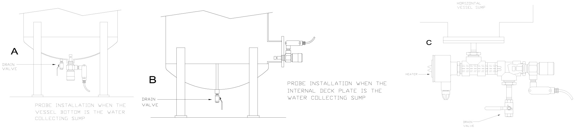
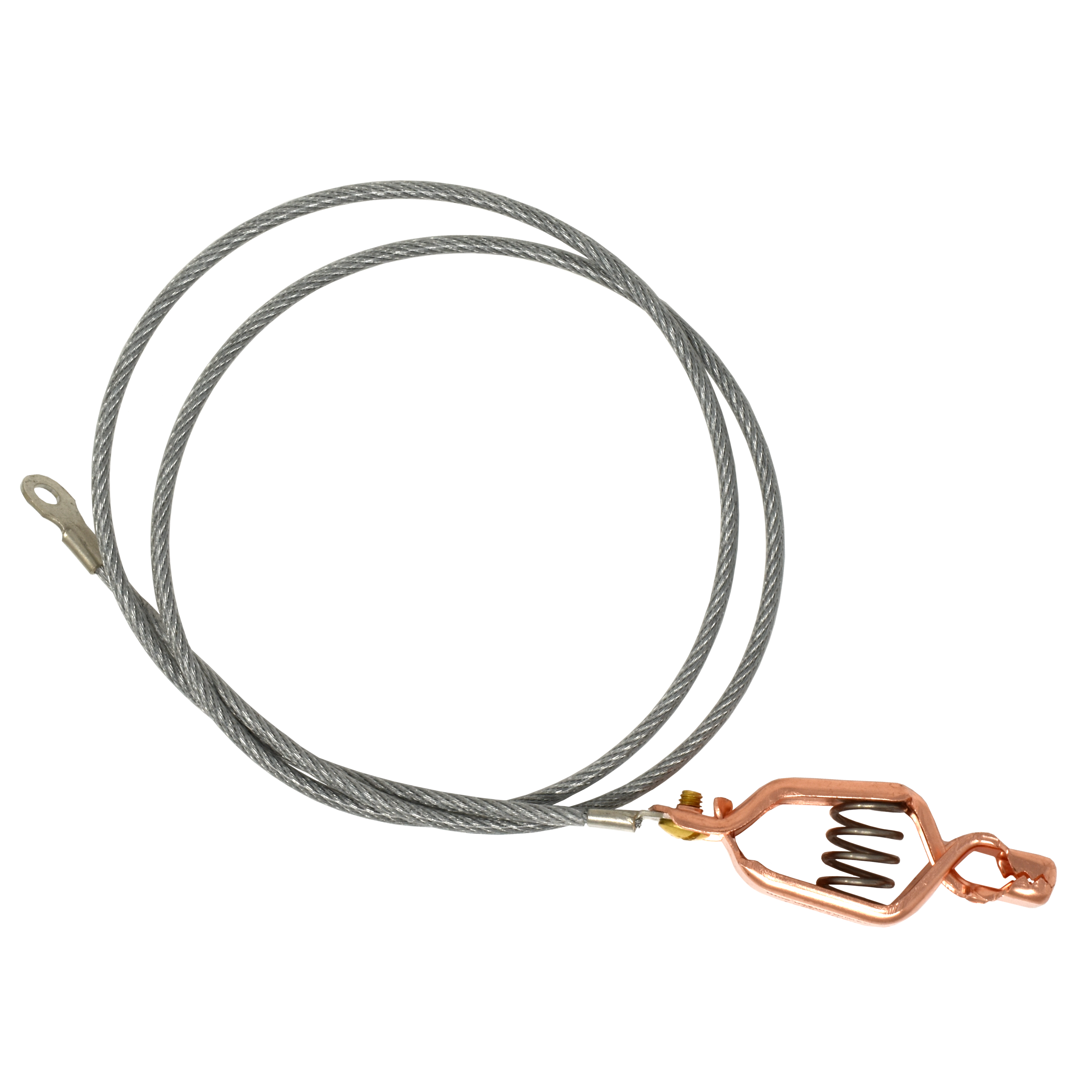
TEST CABLE INSTALLATION should be arranged so that the cable will not be bent at a sharp angle when the yardman pulls upward. Ideally, the opening through which the cable is installed should be as close as possible to the point where the center of the float contacts the top of the tank (see typical arrangement for Style 4). The cable may be attached to the lower face of a pipe cap that will close the top of the access port.

All connection flanges for all styles are 150# ANSI-RF unless otherwise specified.

VERTICAL TANKS
Floating suctions for vertical tanks must be disassembled during installation. The purchase order must specify the manway diameter so that a float can be selected that will pass through. If the arm length/diameter ratio is very great, we add intermediate legs as necessary, especially if the outlet flange is lower than the inlet, causing the arm to remain full when the tank is empty.

If the height of the tank is greater than 75% of the diameter, the arm will rise to such a steep angle that it may hang up. One option is for us to add a restraining cable and let the fuel rise as far above the float as necessary (see Style 3VR). The other option is to add swivel joints and use multiple arms (see style 3VA); we have had to use as many as four in very tall, small-diameter tanks. Special provisions are made to guide the float and arms.

NOTE: We manufacture floating suctions for tanks having floating roofs or pans, but only if we are given drawings of the pan construction so that we can design a track for the rollers.

Bulletin 59: Floating Suction Assemblies2025-01-16T19:31:58+00:00

Bulletin 55: Static Bonding/Grounding Equipment

New Manual Reel

This is the simplest form of static bonding cable reel. Lightweight and durable. Adjustable tension. Horizontal or vertical mount. Right or left hand rewind.

See Bulletin 163

Ametek Cable Reel

The best reel we have ever found. No whipping, no tangles, positively controlled speed with three centrifugal speed brakes. Small, lightweight, and tough.

See Bulletin 54

Ametek Rota-Reel

The Rota-Reel static grounding reel offers a compact and lightweight solution for your grounding needs. Features include automatic retraction, pawl and ratchet locking mechanism, and weather-resistant red powder coat finish. Includes 50’ of uncoated 0.093” diameter galvanized steel cable and a 100 amp copper clip.

ML-700-50R

Static Bonding/Grounding Cable

We offer a wide range of grounding cable. Our cable is made with 7 x 7 galvanized steel or stainless steel wire. It is coated with a tough vinyl or even tougher compounded polyester coating. It is available in clear, high visibility orange, and kink-resistant bright yellow. It can be bought by the foot or on 1,000’ spools.

See Bulletin 98

The Gammon Gator Clamp

At Gammon Technical Products, we have sold grounding clamps and millions of feet of cable over the decades, but we have never made our own unique clamp – until now. The Gammon Gator is designed to surpass all previous clamp designs in every way. It is easier to use, inexpensive, and 100% made in the USA.

  • Aluminum magnesium alloy – light, durable, highly conductive, and corrosion resistant

  • Longer, more comfortable design is ergonomic and easy to use – yet light and inexpensive

  • All high-grade stainless/brass fasteners and spring – includes two cable connections and our unique strain-relief cable attachment design

  • Cycle tested to 100,000 cycles without measurable wear

  • Salt sprays and salt water erosion tested and passed to Mil Spec

  • Drag and run-over tested without breakage or failure

  • Less than 1/2 lb. (0.2kg) & 6” (15.25cm) long

GTP-9654
standard Gator clamp
NSN 5999-01-692-6284

GTP-9654-FP
Gator clamp with integral folding grounding plug

GTP-1101: The Super Clamp

Do not go through the “motions” of grounding. Be sure the aircraft and refueler are really bonded together. This tough clamp conforms to MIL-C-83413/7.

  • Torsion spring provides 30 lbs. jaw pressure on .500” diameter rod; 40 lbs. jaw pressure on .625” diameter rod.

  • When clamped on grounding post, less than 5 ohms resistance from posts to ends of handles.

  • Die cast aluminum alloy assures maximum strength and conductivity.

  • Length: 4.1 inches

  • Weight: 4 ounces

Bonding/Grounding Plug

Includes hex end cap to secure cable

GTP-1097S-1
passivated stainless steel

GTP-1097B
solid brass

GTP-9633-101 Drive-away Grounding Socket Kit

Save money – Less damage

Mount this stainless steel socket to your refueler vehicle with the included attachment kit and use a short grounding cable with a grounding plug on the fixed loading rack. If the driver pulls away without disconnecting – no problem! The flexible grounding socket mounts with a single screw and swings in line with the grounding cable. Eliminate the need for a grounding reel on the loading rack or using the grounding reel on the truck, resulting in the cable wrapped around the rear wheels. Used with bonding/grounding plug (not included).

Bonding/Grounding Clips

Heavy-duty Mueller type clips. 1 dozen minimum order.

Solid copper clips
2 1/2″, 3″, 4″, 6″

Zinc-plated steel clips
4″, 6″

Overwing Bonding/Grounding Assemblies

NFPA requirement, you must bond before removing cap on aircraft

GTP-1094
cable, plug, and clip assembly – 48″

GTP-1095
cable and clip assembly – 90″

Rubber Stop Ball

GTP-1486

For grounding reel cables, these 1 1/4” round stop balls are tough and long lasting.

Cable Stop

GTP-1487

Bulletin 55: Static Bonding/Grounding Equipment2025-01-16T19:31:35+00:00

Bulletin 54: Ametek Hunter Spring Static Bonding Reel

Features

  • For heavy-duty applications

  • Automatic retraction

  • Weather-resistant finish

  • 100 amp alligator clamp termination

Static Bonding Reels provide the automatic retraction and compact storage of 50, 75, and 100 foot cable and clamp assemblies. Designed to function under extreme environmental conditions, the 50 and 75 foot cable length models meet USAF MIL-R-83232B and U.S. Government specification A-A-50696.

A patented latching mechanism holds the cable at any desired length. A slight pull on the cable releases the mechanism causing retraction. Retraction need not be attended. The retraction speed is automatically governed by a special brake assembly designed to limit the retraction speed from two to seven feet per second. Steel components and a cantilever-type frame, which support the reel assembly, are designed to function under the most adverse conditions. Baked-on MIL spec red finish and gasketed drum construction protect operating parts from corrosion. Bearing surfaces are permanently lubricated.

Specifications

CABLE LENGTH

50, 75, or 100 feet

CABLE DIAMETER

1/8″, 3/16″, or 5/32″

CABLE END

Grounding plug, clip, super clamp, or Gator clamp

ELECTRICAL RESISTANCE

10 ohms maximum between clamp and mounting base

LIFE CYCLE

tested to 5,000 cycles

CABLE RETRACTION SPEED

2-7 ft/sec

FINISH

conforms to MIL-Std 808, red paint, Film Designation DG

PACKAGING

conforms to MIL-P 726, Unit Pack – Level A, Shipping Pack – Level B

OPERATING TEMPERATURE

-65° to 125° F

STORAGE TEMPERATURE

-80° to 160° F

Dimensions

How to Order

Bulletin 54: Ametek Hunter Spring Static Bonding Reel2025-01-16T19:31:13+00:00

Bulletin 52: Filter Separator Accessories

Air Eliminators

There is no question in our opinion: these are the most reliable air eliminators money can buy. Stainless steel float and mechanism, Viton A seal, 3/4” NPT in and out. (1/2” on special order), 1/16” air outlet orifice operates up to 208 psi. Air release rate at 150 psi is 6.04 cfm. Larger orifice sizes: 3 available on special order but operating pressures decrease. Structural pressure rating is 250 psi on all models. Repairable replacement parts are available.

GTP-21A
aluminum body air eliminator

GTP-21C
cast iron body air eliminator

STAINLESS STEEL MODEL – High Air Flow
Non-repairable. At 150 psi, releases air at 9.44 cfm. Maximum operation pressure 400 psi. Structural pressure rating 500 psi.

GTP-11-400
stainless steel air eliminator

Socket Adapter for Coalescer Elements

Designed to fit threaded bottom coalescer elements. The socket is 1/2” square drive for torque wrenches and extensions. This adapter is needed to attach a torque wrench to coalescer elements.

GTP-1224
socket adapter for Parker/Velcon

GTP-1224F
socket adapter for Facet

Check Valves

Prevents drain-back

To be installed above the air eliminator

Viton seal – all stainless steel

Designed to fit threaded bottom coalescer elements. The socket is 1/2” square drive for torque wrenches and extensions. This adapter is needed to attach a torque wrench to coalescer elements.

GTP-8982
1/2″ NPT or 1/2″ BSP

GTP-2916-10
3/4″ NPT

GTP-2916-11
3/4″ BSP

GTP-2916-21
3/4″ NPT x 3/4″ BSP

Pressure Relief Valves

Relieves excess pressure caused by thermal expansion of the fuel. Be sure to specify relief pressure setting.

Note: 150psi is our standard pressure relief valve setting. Other settings are special order and are non-refundable.

GTP-803S
Carbon steel
Available settings from 15 to 3500 psi
3/4” male x 1” female
Also available in stainless steel

GTP-803B-1
Bronze
Available settings from 5 to 300 psi, non-certified
3/4” male x 3/4” female

GTP-1357V
Bronze
Available settings from 75 to 200 psi (150psi standard), non-certified
3/4” male x 3/4” female

Bulletin 52: Filter Separator Accessories2025-01-16T19:30:39+00:00
Go to Top